Introduction to Photoelectric Sensor Interference
Photoelectric sensors are indispensable components in modern industrial automation, providing reliable object detection, positioning, and counting. However, their performance in harsh field environments is often compromised by various forms of interference. This interference can lead to false triggering, missed detections, and ultimately, costly production downtime. Understanding the sources and mechanisms of this interference is the first critical step for any electrical engineer tasked with maintaining robust system integrity. The core principle of operation—emitting a light beam (visible, infrared, or laser) and detecting its reflection or interruption—is inherently susceptible to environmental contaminants and competing energy sources.
Primary Sources of External Interference
The most common interference sources originate from the sensor's surroundings. Ambient light is a pervasive culprit, particularly strong sunlight, which can flood the receiver and mask the sensor's own signal. Strobe lights, welding arcs, and other high-intensity industrial lighting produce similar effects. Electrical noise from high-power equipment like variable frequency drives (VFDs), motors, solenoids, and switching power supplies can induce voltage spikes and ground loops, corrupting the sensor's sensitive electronic signals. Furthermore, physical obstructions such as dust, steam, oil mist, or chemical vapors can attenuate or scatter the light beam, reducing effective sensing range and reliability.

Internal and Cross-Talk Interference Challenges
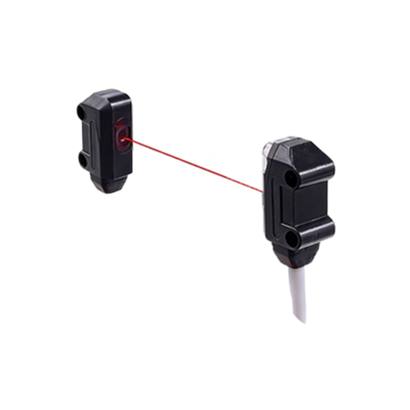
Interference is not solely external. In dense installations, multiple photoelectric sensors can interfere with each other, a phenomenon known as cross-talk. This occurs when the light beam from one sensor's emitter is detected by the receiver of a nearby sensor. Modern sensors often use modulated light pulses at specific frequencies to distinguish their own signal from background light, but if two nearby sensors operate at the same or harmonically related frequencies, cross-talk can still occur. Additionally, internal electronic noise from the sensor's own circuitry or power supply instability can generate erratic behavior.
Strategies for Optical Interference Mitigation
Combating optical interference requires both physical and electronic strategies. Selecting the appropriate light source is fundamental. Infrared sensors are less susceptible to visible ambient light, while laser sensors offer a highly collimated beam that is more resistant to dispersion by particulates. Using sensors with polarized lenses can help reject specular reflections from shiny surfaces, a common source of false readings. Physical measures include installing protective shrouds, tubes, or baffles to shield the lens from direct ambient light and contaminants. Ensuring lenses are kept clean through scheduled maintenance or employing sensors with built-in lens contamination detection is also crucial.
Solutions for Electrical Noise Suppression
Mitigating electrical noise demands a focus on proper installation and wiring practices. Using shielded cables, with the shield properly grounded at only one end (typically the controller end), is essential to prevent ground loops and contain electromagnetic interference (EMI). Routing sensor cables away from high-power lines, using separate conduits, and minimizing cable length reduce the antenna effect. Employing filters, such as ferrite cores on cables near noise sources, can attenuate high-frequency noise. For sensors powered by DC supplies, ensuring a stable, clean power source with adequate filtering is non-negotiable. In extreme cases, opting for sensors with robust noise immunity ratings or those employing differential signal transmission can provide added resilience.
Preventing Sensor Cross-Talk
Preventing cross-talk involves careful system planning and sensor selection. When installing multiple sensors in close proximity, choose models that offer selectable operating frequencies or synchronization capabilities. Synchronized sensors can be set to emit light pulses in a timed sequence, preventing their beams from being active simultaneously. Alternating between different sensing modes (e.g., using retro-reflective and diffuse sensors adjacent to each other) or physically orienting sensors so their beams are not parallel can also minimize risk. Increasing the physical separation between sensors, when layout permits, remains a simple yet effective solution.
System Design and Diagnostic Best Practices
Ultimately, resilience to interference is best achieved through proactive system design. Conducting a thorough site survey before installation to identify potential noise and light sources is invaluable. Selecting sensors with high ingress protection (IP) ratings suitable for the environment (e.g., IP67 for washdown areas) protects against physical contaminants. Implementing diagnostic tools, such as sensors with signal strength indicators or IO-Link capability, allows for continuous monitoring of performance and early detection of degrading conditions. Regular functional testing under actual operating conditions, not just at startup, ensures the entire sensing system maintains integrity over time.