Introduction to Photoelectric Sensor Laser Technology
Photoelectric sensors utilizing laser technology represent a significant advancement in industrial automation and precision measurement. Unlike standard LED-based photoelectric sensors, laser sensors employ a highly focused, coherent light beam. This fundamental difference provides exceptional performance in applications requiring high precision, long sensing distances, and detection of minute objects. The core of this technology lies in its schematic design and the precise control of laser emission and reception. The laser diode, a key component, emits a narrow-wavelength light beam, typically in the visible red or infrared spectrum. This focused beam minimizes dispersion, allowing for precise spot detection even over considerable distances, a critical factor in complex industrial environments where accuracy is paramount.
Core Components and Schematic Layout
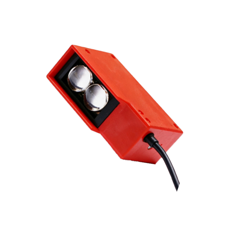
A standard laser photoelectric sensor schematic comprises several integral components. The primary circuit includes the laser driver, the laser diode itself, the receiving element (usually a phototransistor or photodiode), and a signal processing unit. The laser driver circuit is crucial; it provides a stable, regulated current to the laser diode, ensuring consistent light output and protecting the diode from current surges. The emitted laser beam is directed towards the target. The receiving circuit is designed to detect the reflected or interrupted beam. In a retro-reflective or diffuse mode, the photodetector converts the received light intensity into a proportional electrical current. This weak signal is then amplified and processed by a comparator circuit within the signal processing unit, which finally generates a clean, digital output signal (e.g., PNP or NPN) to interface with PLCs or other control systems.
Operating Principles: Through-Beam, Retroreflective, and Diffuse
The schematic implementation varies based on the operating mode. In a through-beam (or opposed) mode, the schematic separates the emitter and receiver into two distinct units. The laser driver circuit is housed in the emitter, and a dedicated receiver circuit with a photodetector is in the separate unit. The principle is straightforward: an object is detected when it interrupts the beam. The retroreflective mode integrates both emitter and receiver in one housing. The schematic includes optics to separate the emitted and received light paths. The laser beam is projected onto a reflector and bounced back to the receiver. Detection occurs when the beam is blocked. The diffuse (or proximity) mode is the most integrated. The emitter and receiver are positioned at an angle within the same housing. The sensor detects light scattered back from the target itself. The receiver circuit in this mode is highly sensitive to distinguish the weak reflected signal from ambient light noise.
Signal Processing and Noise Immunity
A critical part of the laser sensor schematic is the signal processing chain. After the photodetector generates a current, a transimpedance amplifier converts it to a voltage. This analog signal is often filtered to remove noise from ambient light, typically 50/60 Hz from artificial lighting. Advanced sensors incorporate modulation/demodulation techniques. The laser driver modulates the laser beam at a high frequency (e.g., several kHz). The receiver circuit is tuned to this specific frequency, effectively ignoring all other light sources. This schematic approach provides superior immunity to optical noise and enables stable detection even in brightly lit conditions. Furthermore, automatic gain control (AGC) circuits may be included to compensate for varying target reflectivity or distance, ensuring a consistent signal level for the comparator.
Application-Specific Schematic Considerations
Designing a laser photoelectric sensor schematic requires tailoring for specific applications. For high-speed counting on production lines, the schematic prioritizes fast response times, involving high-speed comparator circuits and minimal signal delay. For precision positioning or edge detection, the schematic focuses on the sharpness of the laser spot and the resolution of the receiving circuit. In safety applications, such as laser guards, the schematic incorporates redundancy and self-checking circuits to meet safety integrity levels (SIL or PL). For long-range detection, the laser driver must provide sufficient power while eye-safety regulations (IEC 60825-1) dictate strict control over emission characteristics, directly influencing the driver circuit design and often requiring built-in monitoring features.
Advantages Over Conventional LED Sensors
The schematic advantages of laser-based sensors are evident in their performance. The coherent, narrow beam allows for precise optical design, enabling the detection of very small objects. The high energy density of the laser spot provides a stronger return signal, permitting longer sensing ranges compared to LED types. The monochromatic nature of laser light simplifies optical filtering in the receiver schematic, enhancing ambient light rejection. This allows for reliable operation in challenging environments. The ability to focus the beam to a fine point is invaluable in applications like precise assembly, wafer handling, or detecting thin wires, where standard photoelectric sensors would lack the necessary resolution.
Future Trends in Laser Sensor Design
The evolution of laser photoelectric sensor schematics is driven by miniaturization and intelligence. Integration of Application-Specific Integrated Circuits (ASICs) consolidates the driver, amplifier, filter, and processor into a single chip, reducing size and power consumption. The incorporation of digital signal processors (DSPs) allows for more sophisticated algorithms for background suppression, distance measurement via time-of-flight principles, and output of analog values proportional to distance. Furthermore, connectivity features like IO-Link are becoming standard, requiring additional communication circuitry in the schematic. This enables parameter setting, condition monitoring, and advanced diagnostics directly from the control system, pushing laser sensors from simple switches towards smart, data-providing devices in the Industrial Internet of Things (IIoT) landscape.