Introduction to 220V AC Sound and Light Sensors
In the realm of industrial automation and building management, 220V AC sound and light sensors represent a critical category of sensing devices. These sensors are designed to operate directly on standard mains voltage, eliminating the need for additional power supplies or voltage converters in many installations. A sound and light sensor, often referred to as a combined or multi-parameter sensor, integrates acoustic (sound) and optical (light) sensing capabilities into a single, robust housing. This dual functionality allows for sophisticated control logic, such as activating lighting or ventilation systems only when both ambient light is low and specific sound levels (like occupancy noise) are detected. The 220V AC specification indicates that the sensor is powered by and often switches the same alternating current line voltage, making it a self-contained control node ideal for retrofitting existing electrical systems.
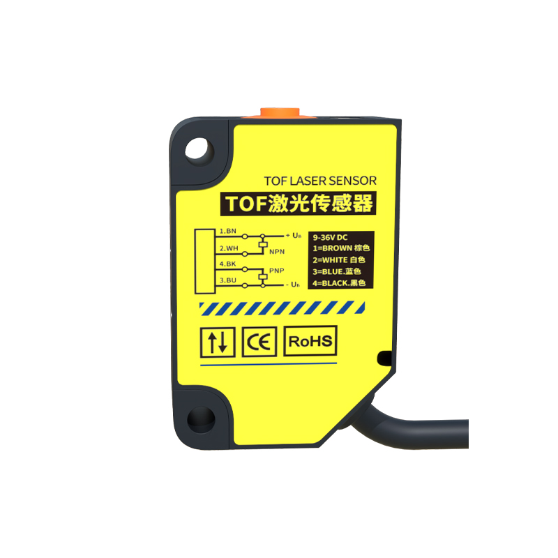
Core Operating Principles and Technology
The operational heart of a 220V sound and light sensor lies in its two distinct sensing modules. The sound detection component typically utilizes a high-sensitivity electret condenser microphone coupled with an amplifier and comparator circuit. This circuit is tuned to trigger an output relay when sound pressure levels exceed a pre-set threshold, which is often adjustable via a potentiometer on the device. The light sensing module employs a photoresistor (LDR) or a photodiode to measure ambient illuminance. As light intensity falls below a configurable setpoint, the sensor's internal logic is primed for the sound trigger. The integrated control logic, usually based on a simple microcontroller or discrete logic ICs, processes inputs from both sensors according to a defined function (e.g., AND logic). The final output stage involves a solid-state relay (SSR) or an electromechanical relay capable of switching the 220V AC load directly.
Key Design Features and Specifications
When selecting a 220V AC sound and light sensor, several technical specifications are paramount. The input voltage range is typically 180V-240V AC, 50/60Hz, ensuring compatibility with most grid standards. The load capacity of the internal relay, measured in amperes (e.g., 10A, 16A), dictates the maximum power of connected devices like lighting arrays or fans. Sensitivity adjustments are crucial; sound sensitivity is measured in decibels (dB) with an adjustable range (e.g., 50-90 dB), while light sensitivity is measured in lux (e.g., adjustable from 10-2000 lux). Additional features may include a time-delay function, which keeps the output active for a set duration after the triggering event ceases, preventing rapid cycling. The housing is invariably designed with an IP (Ingress Protection) rating, such as IP65, for dust and water resistance in harsh industrial or outdoor environments.
Typical Application Scenarios in Industry
The applications for these sensors are diverse and driven by efficiency and automation needs. In warehouse and storage facilities, they are deployed to control high-bay lighting, ensuring lights are only on in aisles where activity (sound) is present and natural light is insufficient, leading to significant energy savings. In stairwells, corridors, and parking garages of commercial buildings, they provide automatic, demand-based lighting, enhancing safety while reducing operational costs. Industrial workshops with variable occupancy can use them to control ventilation systems, activating air exchange when machinery noise indicates human presence. They are also found in security systems as a supplementary trigger, where an unexpected sound in a darkened, secured area can activate alarms or surveillance recordings.
Installation, Wiring, and Configuration Guidelines
Proper installation is critical for reliable operation. The sensor must be mounted in a location representative of the area to be monitored, avoiding direct sound sources (like constant machine hum) or light sources (like direct sunlight or adjacent fixtures) that could cause false triggering. Standard wiring involves connecting the Live (L) and Neutral (N) 220V AC mains wires to the sensor's power terminals. The output switched live wire is then connected from the sensor's relay terminal to the load (e.g., light fixture). A separate earth ground connection is mandatory for safety. Following power-up, configuration involves using a small screwdriver to adjust the sensitivity potentiometers for light and sound, and often a third for time delay. It is recommended to perform calibration during typical ambient conditions of the installation site.
Advantages Over Separate Sensing Solutions
The integration of sound and light sensing into a single 220V AC device offers distinct advantages. It simplifies system design and reduces installation time and cost by requiring only one device to be mounted and wired. The built-in logic reduces the need for external controllers or programmable logic controllers (PLCs) for basic automated switching tasks. By combining parameters, it drastically reduces false activations—a light sensor alone might turn lights on at dusk in an empty room, while a sound sensor alone might activate with noise during a bright day. The combined approach ensures activation only under the intended environmental conditions, improving system intelligence and efficiency. Furthermore, maintenance is streamlined as there is only one device to service.
Common Troubleshooting and Maintenance Points
Even robust sensors may encounter issues. Common problems include failure to activate, which can stem from incorrect sensitivity settings, misplacement, or a faulty relay. Continuous activation might be caused by ambient sound or light levels permanently exceeding thresholds. Initial troubleshooting should always involve verifying the power supply and re-checking sensitivity and delay settings. Use a sound level meter and lux meter to objectively measure conditions at the sensor's location against its settings. Physically, ensure the microphone inlet and light sensor window are not obstructed by dust, dirt, or insect ingress, which is a frequent issue in industrial settings. Periodic cleaning as per the IP rating guidelines is essential for long-term reliability. For electrical faults, testing the relay output with a multimeter (with power disconnected) can determine if the internal switching component has failed.