Introduction to Photoelectric Tachometers
A photoelectric sensor tachometer is a non-contact instrument designed for precise rotational speed measurement. It operates on the fundamental principle of converting light beam interruptions into electrical pulses. The core system consists of a light source, typically an LED or laser, a photodetector, and a signal processing unit. When the rotating object, often fitted with a reflective mark or a slotted disc, passes through or reflects the light beam, it modulates the light reaching the detector. This modulation generates a pulse train whose frequency is directly proportional to the rotational speed. The processing unit calculates the RPM (Revolutions Per Minute) or RPS (Revolutions Per Second) from this frequency, displaying the result digitally. This method offers significant advantages over contact methods like mechanical tachometers, eliminating slip, wear, and loading effects on the measured shaft.
Core Working Principles and Components
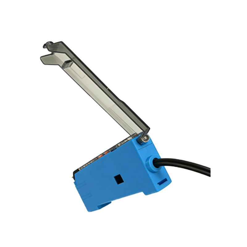
The operation can be categorized into two primary modes: transmissive and reflective. In the transmissive mode, the light source and detector are aligned opposite each other. A slotted or perforated disc attached to the rotating shaft periodically interrupts the beam. Each interruption creates a pulse. Reflective mode employs a single housing containing both the emitter and detector. A reflective mark on the target surface reflects light back to the sensor once per revolution. Advanced models use infrared light to minimize ambient light interference. The key components include a stable oscillator for time-base generation, a high-speed counter for pulse accumulation, and a microcontroller for frequency-to-RPM conversion. Signal conditioning circuits are critical for filtering noise and shaping the pulse waveform to ensure accurate counting, especially at very high or low speeds.
Advantages in Industrial Applications
The non-contact nature of photoelectric tachometers delivers unparalleled benefits in demanding industrial environments. Firstly, they impose zero mechanical load, making them ideal for measuring the speed of delicate or low-torque mechanisms. Secondly, they offer high accuracy and resolution, capable of measuring speeds from a few RPM to several hundred thousand RPM. Their fast response time allows for real-time monitoring and control in dynamic systems. Durability is another key advantage; with no moving parts in contact with the target, they suffer minimal wear and require little maintenance. They are also versatile, easily adaptable to different machine setups by adjusting the sensor position or reflective tape. This makes them superior to proximity sensors when measuring non-metallic objects or where magnetic fields are present.
Common Industrial Use Cases
These instruments are ubiquitous across manufacturing and automation. A primary application is motor speed verification and control in conveyor systems, pumps, fans, and spindles. In the automotive industry, they are used to measure engine RPM during testing and assembly. Printing and packaging machinery rely on them for precise web speed synchronization to prevent material tearing or misalignment. They monitor turbine and generator shaft speeds in power generation for protection against overspeed conditions. In textile manufacturing, they control the speed of spinning frames and looms. Furthermore, they are integral to laboratory research for characterizing prototype machinery and in quality assurance processes to ensure products meet specified rotational speed tolerances.
Critical Selection Criteria
Choosing the correct photoelectric tachometer requires careful consideration of several technical parameters. Measurement range is paramount; ensure the sensor's maximum frequency response exceeds the target's maximum speed. Resolution and accuracy specifications must align with process requirements. The sensing distance and required spot size determine the installation geometry. Environmental factors are crucial: the sensor must have an appropriate Ingress Protection (IP) rating for dust and moisture, and withstand operational temperatures, vibrations, and ambient light conditions. Output options vary, including analog (4-20mA, 0-10V), digital pulses, or direct communication protocols like RS-485 or IO-Link for integration into PLCs and data acquisition systems. Finally, consider the ease of alignment and the availability of mounting accessories.
Installation and Calibration Best Practices
Proper installation is critical for reliable operation. For reflective sensing, ensure the mark provides high contrast, is clean, and is sized appropriately for the sensing distance. The background surface should be non-reflective and dark. Precise alignment of the sensor perpendicular to the target path is necessary to maximize signal strength. In transmissive setups, ensure the disc slots are clean and the alignment between emitter and detector is perfect. Minimize cable run lengths and route them away from sources of electrical noise like motor drives. Calibration typically involves programming the number of pulses per revolution into the instrument. For high-accuracy applications, a master tachometer or strobe light can be used to verify and fine-tune the readings. Regular maintenance should include lens cleaning and checking the integrity of reflective marks.
Troubleshooting Common Issues
Common problems often stem from installation or environmental factors. Erratic or zero readings usually indicate poor alignment, excessive sensing distance, a dirty lens, or a degraded reflective mark. Verify the light source is active. Electrical noise can cause false counts; using shielded cables and proper grounding is essential. If the measured speed is consistently inaccurate, check the pulses-per-revolution setting. Saturation of the detector from strong ambient light can be mitigated by using sensors with modulated light sources or installing physical shrouds. For intermittent operation, inspect all connectors for looseness and cables for damage. Understanding the instrument's diagnostic indicators, if available, can quickly pinpoint issues related to signal strength or supply voltage.
Future Trends and Technological Advancements
The evolution of photoelectric tachometers is closely tied to advancements in optoelectronics and digital processing. Modern units are becoming more intelligent, integrating self-diagnostic features and adaptive algorithms that compensate for deteriorating reflective marks or lens contamination. Miniaturization allows embedding into tighter spaces. The integration of wireless connectivity (e.g., Bluetooth, Wi-Fi) enables easier data logging and integration into Industrial Internet of Things (IIoT) networks for predictive maintenance analytics. Furthermore, the combination of speed measurement with other sensor data, such as vibration or temperature, into multifunctional devices provides a more comprehensive health monitoring solution for rotating equipment, driving efficiency and reducing unplanned downtime.