Introduction to Proximity Switch Center Threads
The center thread of a proximity switch sensor, often referred to as the mounting thread, is a fundamental yet critical mechanical feature. It serves as the primary interface for installing the sensor into a machine, panel, or fixture. While the electronic sensing element captures the attention for its functionality, the integrity and precision of this threaded section are paramount for reliable, long-term operation in industrial environments. A poorly designed or manufactured thread can lead to installation difficulties, insecure mounting, and ultimately, sensor failure due to vibration or misalignment. This article delves into the technical specifications, standards, and practical considerations surrounding the center thread in inductive and capacitive proximity sensors.
Standard Thread Specifications and Global Norms
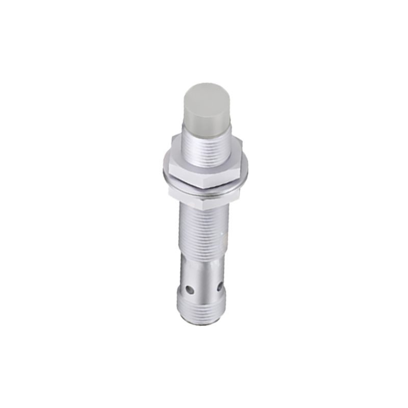
Proximity switch threads are predominantly standardized to ensure compatibility with a wide range of mounting hardware. The most common thread forms are metric (M) and unified (UNF/UNC). Metric threads, such as M8, M12, M18, and M30, are globally prevalent, especially following ISO standards. For instance, an M12 x 1.0 thread indicates a 12mm major diameter with a 1.0mm pitch. In North America, NPT (National Pipe Taper) threads are also common for certain applications requiring a sealed connection. Engineers must specify the thread type, size, and pitch accurately. The thread length, from the sensor's housing to the first full thread, is also a specified dimension crucial for ensuring the sensor can be properly tightened against a lock nut or into a threaded hole.
Material Selection and Thread Durability
The material of the sensor body, and by extension the thread, directly impacts durability and application suitability. Stainless steel (typically 303 or 316 grades) is the gold standard for threads, offering excellent corrosion resistance, mechanical strength, and wear characteristics in harsh environments involving coolants, washdowns, or chemicals. Nickel-plated brass is another common choice, providing good corrosion resistance at a lower cost for less demanding applications. For plastic-bodied sensors, the thread is often molded from robust engineering plastics like PBT or PVDF. The choice of material must align with the environmental IP (Ingress Protection) rating and the mechanical stresses expected during installation and operation.
Mounting Techniques and Installation Best Practices
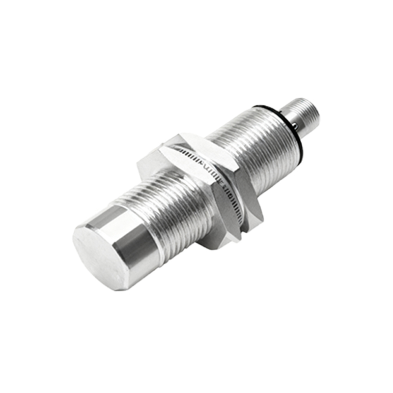
Correct installation is vital to protect the thread and ensure sensor performance. A standard method involves using two hex nuts as lock nuts. The sensor is inserted through a mounting hole, and the nuts are tightened against each other on the threaded section to secure it firmly. Over-tightening is a common pitfall that can strip threads, crack sensor housings, or distort the sensing face, altering its characteristics. Always use a calibrated torque wrench and adhere to the manufacturer's specified torque values, which are typically low (e.g., 10-20 Nm for an M18 sensor). For through-hole mounting, ensure the hole is clean, deburred, and of the correct diameter to prevent cross-threading.
The Impact of Thread Design on Sensing Performance
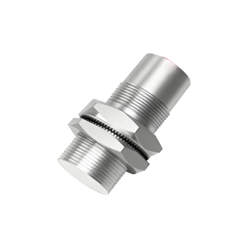
While seemingly separate, the mechanical thread design can influence electrical performance. In shielded (flush-mountable) inductive sensors, the threaded metal barrel is often part of the active sensing face's shielding. This design allows the sensor to be mounted flush in metal without causing false triggers, but it slightly reduces the nominal sensing distance. Unshielded (non-flush) sensors have their sensing coil extended to the front, offering longer ranges but requiring a non-metallic surround when mounted. The thread's proximity to the sensing area means that using incorrect washers or mounting in conductive material can affect the sensor's field and must be considered during selection.
Special Thread Types and Custom Solutions
Beyond standard straight threads, several specialized types exist. Tapered threads like NPT are used where a pressure-tight seal is needed without additional sealing elements. Some sensors feature a through-hole design where the thread is internally bored, allowing for the passage of wires or other components. For high-vibration applications, sensors with prevailing torque lock nuts or other thread-locking features are available. Manufacturers also offer custom threading services for OEM applications requiring unique sizes, left-hand threads, or specific material grades to integrate seamlessly into proprietary machinery.
Maintenance, Inspection, and Troubleshooting
Regular inspection of the sensor's threaded portion is a key part of preventative maintenance. Look for signs of wear, corrosion, metal shavings (galling), or physical damage. Damaged threads can often be repaired using a thread chaser or tap of the correct size, but care must be taken to avoid introducing metal debris into the sensor's interior. If a sensor is frequently removed