Understanding Proximity Sensor Fundamentals
Proximity sensors are non-contact devices designed to detect the presence or absence of an object within their sensing field. They operate on various principles, primarily inductive, capacitive, ultrasonic, and photoelectric. Inductive sensors detect metallic objects, capacitive sensors can detect both metallic and non-metallic materials, ultrasonic sensors use sound waves for detection over longer ranges, and photoelectric sensors utilize light beams. The core function is to provide a reliable electrical signal output—typically a switching signal—when a target enters the predefined detection zone. This fundamental operation makes them indispensable for automation, positioning, counting, and inspection tasks across manufacturing, packaging, and material handling industries. Selecting the correct type is the first critical step in any application.
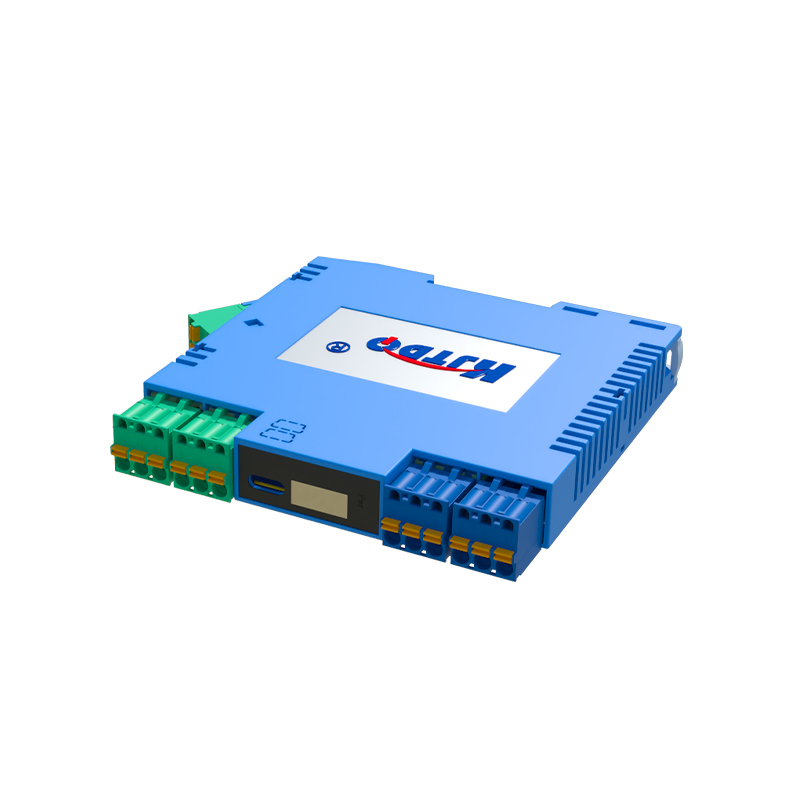
Key Installation and Mounting Considerations
Proper installation is paramount for reliable sensor performance. First, ensure the sensor is mounted securely to prevent vibration-induced false triggers or physical damage. For inductive and capacitive sensors, maintain the specified sensing distance, accounting for the reduction factor for different metals or materials. Always consider the mounting environment; flush-mountable sensors can be installed embedded in metal, while non-flush types require a clear lateral area. Provide adequate clearance between multiple sensors to prevent mutual interference, often referred to as crosstalk. For threaded barrel sensors, use the correct locknut and torque to specification. Protect the sensing face from accumulation of dust, chips, or coolant, as this can severely degrade performance, especially for capacitive and optical types.
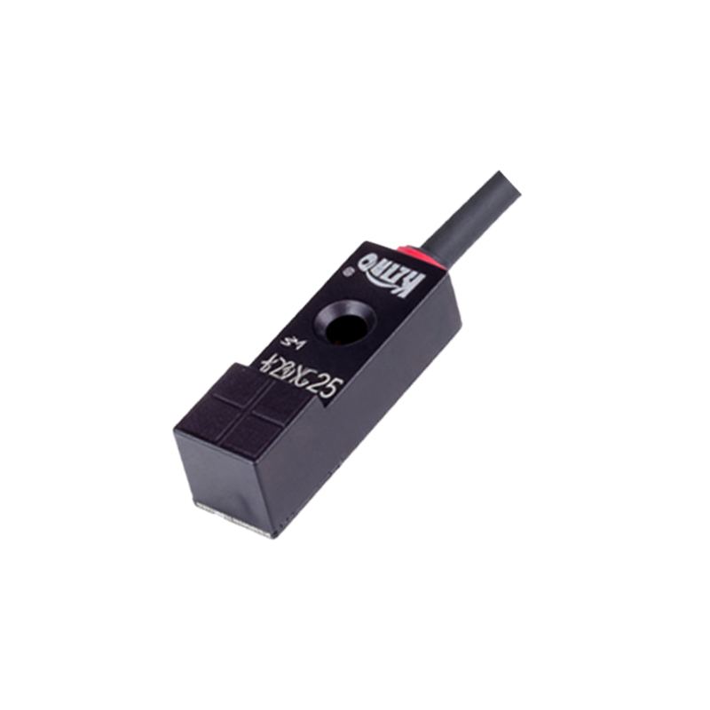
Electrical Wiring and Connection Best Practices
Correct electrical integration is crucial. Always refer to the sensor's datasheet for its operating voltage (commonly 10-30V DC or 90-250V AC), output type (PNP/NPN, NO/NC), and current rating. Use shielded cables in electrically noisy environments, grounding the shield at the controller end only. For DC sensors, strictly observe polarity to prevent damage. Implement protective circuits such as flyback diodes for inductive loads (relays, solenoids) connected to the sensor output to suppress voltage spikes. Ensure the load current does not exceed the sensor's maximum switching capacity. For long cable runs, consider voltage drop and use cables with appropriate conductor gauge. Neatly route wiring away from high-power cables to minimize electromagnetic interference.
Optimizing Sensing Performance and Range
Achieving optimal sensing distance and repeatability requires fine-tuning. The rated sensing distance (Sn) is defined under ideal conditions. In practice, factors like target material, size, shape, and approach direction affect the actual operating point. For inductive sensors, use a ferrous metal target of standard size (often the sensor's face diameter) for maximum range. For non-standard targets, apply a correction factor. Adjust the sensitivity potentiometer on adjustable sensors to compensate for challenging conditions, but avoid setting it too high, which can cause instability due to background interference. Regularly test the sensor with the actual target material under real operating temperatures, as temperature drift can affect the sensing characteristics.
Troubleshooting Common Operational Issues
Systematic troubleshooting resolves most field issues. If a sensor fails to detect, first verify power supply voltage at the sensor terminals under load. Check for physical damage or contamination on the sensing face. Confirm the target material, size, and approach speed are within specifications. For erratic operation, investigate electrical noise by temporarily routing the sensor cable away from noise sources. Use an oscilloscope to check for a clean switching signal. If the output is latched on, the load may be drawing excessive current or there could be an internal failure. For capacitive sensors, false triggering is often due to environmental changes like humidity or nearby moving objects; adjust the sensitivity accordingly. Always compare current behavior against a known-good baseline.
Implementing Advanced Application Techniques
Beyond simple detection, proximity sensors enable sophisticated functions. For precise positioning, use multiple sensors in a graduated array. For speed measurement, employ two sensors to calculate the time a target takes to pass between them. In counting applications, ensure the target size and spacing are sufficient for the sensor's response and release time to reset. For liquid level detection with capacitive sensors, carefully calibrate the sensitivity to distinguish between the tank wall and the liquid medium. In hazardous areas, select intrinsically safe or explosion-proof certified models. Integrating sensors with PLCs or controllers allows for complex logic, such as conditional triggering or data logging for predictive maintenance, maximizing the value of the sensing data.
Developing a Proactive Maintenance Routine
Preventive maintenance ensures long-term reliability and avoids unplanned downtime. Establish a regular inspection schedule to clean sensing faces from oil, dust, or metal shavings using appropriate solvents. Check for loose mounting hardware or connectors. Periodically verify the sensing distance and