Introduction to Mutual Interference in Proximity Sensors
In industrial automation, metal proximity sensors are indispensable components for non-contact detection, position sensing, and object counting. However, a common and often overlooked challenge is mutual interference, also known as "cross-talk" or "mutual influence," which occurs when two or more sensors are installed in close proximity to each other. This phenomenon can lead to erratic behavior, false triggering, and a significant reduction in system reliability. Understanding the root causes and implementing effective mitigation strategies is crucial for any engineer designing or maintaining automated systems. This article delves into the technical principles behind this interference and provides practical solutions to ensure optimal sensor performance.
The Core Mechanism of Inductive Proximity Sensors
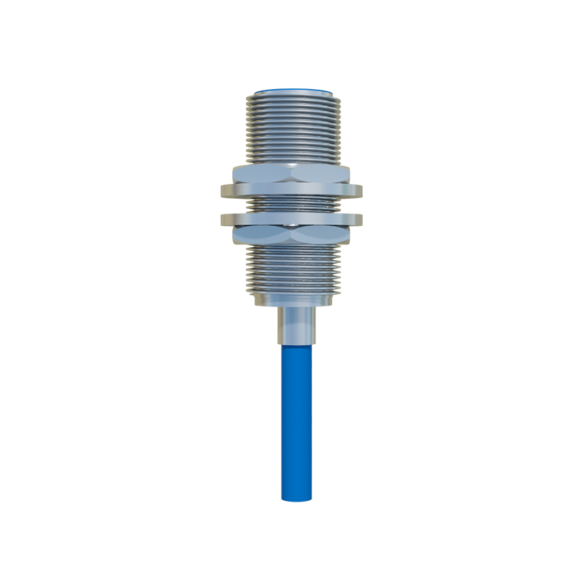
To comprehend mutual interference, one must first understand how a standard inductive proximity sensor operates. At its heart is an oscillator circuit that generates a high-frequency electromagnetic field from a coil wound around a ferrite core. When a metallic object enters this active field, eddy currents are induced on the object's surface. These eddy currents draw energy from the oscillator, causing its amplitude to decrease. This change is detected by a threshold circuit, which subsequently switches the sensor's output state. The sensor's nominal sensing distance (Sn) is defined under ideal conditions with a standard target. The effective operating distance can be influenced by the target's material, size, and shape.
Primary Causes of Mutual Interference
Mutual interference arises primarily from the overlapping of the electromagnetic fields generated by adjacent sensors. When sensors are mounted too closely, the field from one sensor can be detected by its neighbor. This can cause the neighboring sensor to interpret this external field as the presence of a metal target, leading to a false trigger. Conversely, the presence of an actual target for one sensor might be masked or its effective sensing distance drastically reduced due to the influence of the adjacent sensor's field. The severity of interference depends on several key factors: the physical distance between sensors, their operating frequency, their mounting orientation (face-to-face is worst), the type of metal housing (shielded or unshielded), and the power supply configuration.
Analyzing Different Mounting Scenarios
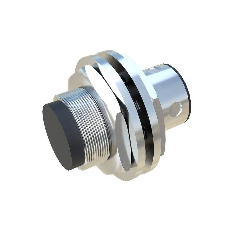
The risk and type of interference vary significantly with mounting arrangement. In a side-by-side configuration, unshielded sensors are highly susceptible as their magnetic fields extend laterally. Shielded sensors, whose fields are concentrated axially forward, perform better but still require careful spacing. A face-to-face mounting is the most problematic, as sensors are directly within each other's primary detection zone. Even shielded sensors can interfere in this setup. Mounting sensors on opposite sides of a metal barrier can also be problematic if the barrier is thin, as the electromagnetic field may penetrate it. Engineers must consult the manufacturer's datasheet for specific minimum separation distances, which are typically expressed as multiples of the sensor's diameter or sensing distance.
Technical Strategies for Mitigation
Several proven techniques can eliminate or minimize mutual interference. The most straightforward method is to increase the physical separation between sensors. As a rule of thumb, a distance of at least three to five times the sensor diameter (for unshielded) is often recommended. Using alternating current (AC) and direct current (DC) sensors on the same system can help, as they operate at different frequencies. Synchronization or phase control is an advanced feature available in some sensor families. Here, sensors are connected to a common synchronization line, causing them to operate in a pulsed, out-of-phase manner, ensuring their active periods do not overlap. Selecting shielded (flush-mountable) sensors over unshielded (non-flush) types greatly reduces lateral field emission and is preferred in dense installations.
Advanced Solutions and Best Practices
For complex applications with extreme space constraints, engineers can turn to more advanced solutions. Sensors with different operating frequencies (e.g., low-frequency and high-frequency models) can be intermixed to reduce resonant coupling. Ensuring a stable, well-regulated power supply with proper filtering is essential, as noise on the supply lines can exacerbate interference issues. Proper grounding of sensor housings and metal machine frames is critical. In programmable logic controller (PLC) systems, software debouncing filters or timing delays can be implemented to ignore transient false signals, though this is a corrective rather than preventive measure. Ultimately, the best practice is to prototype and test the actual sensor layout under real operating conditions before finalizing the design.
Conclusion and System Reliability
Mutual interference between metal proximity sensors is a predictable physical phenomenon, not a random fault. By applying a systematic approach—understanding sensor technology, carefully planning layout and spacing, selecting appropriate sensor types, and utilizing advanced features like synchronization—engineers can design robust and interference-free sensing systems