Understanding the Power Light's Role
The power indicator light on an automotive photoelectric sensor is a critical diagnostic tool. It provides immediate visual feedback on the sensor's operational status. A steady, solid light typically signifies normal operation, where the sensor is receiving correct voltage and is functionally active. Conversely, a flashing or blinking power light is a deliberate signal from the sensor's internal circuitry indicating an anomaly. This behavior is a form of coded communication, designed to alert technicians and engineers to specific issues without requiring immediate connection to a diagnostic scan tool. Interpreting these flash patterns is the first essential step in any troubleshooting procedure.
Common Causes of Intermittent Flashing
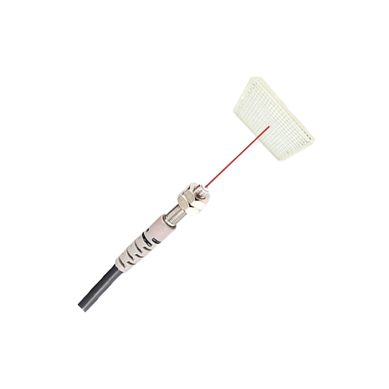
Several underlying issues can trigger a flashing power indicator. The most frequent culprit is an unstable or inadequate power supply. Photoelectric sensors have strict voltage operating ranges, often between 10-30V DC. Voltage drops below the minimum threshold, excessive ripple, or electrical noise from other components can cause the sensor's power regulation circuit to reset intermittently, manifesting as a flashing light. Poor wiring connections, corroded terminals, or damaged cables leading to voltage loss are prime suspects. Another common cause is sensor overload or a short circuit in the load circuit connected to the sensor's output. The sensor's protection circuitry may cycle on and off to prevent damage, resulting in a blinking power LED.
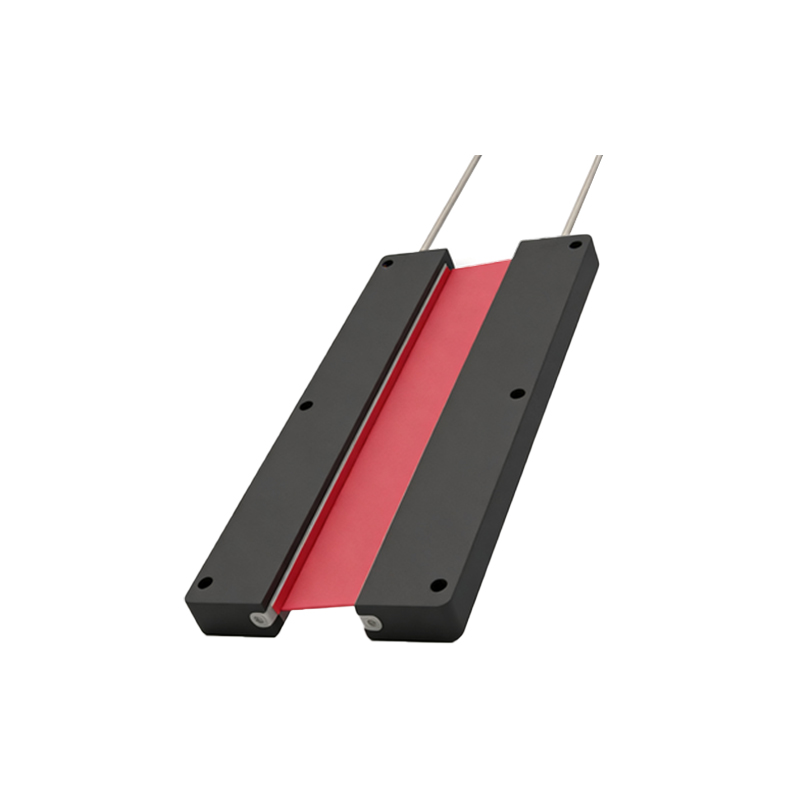
Diagnostic Procedure and Voltage Checks
A systematic approach is vital for efficient diagnosis. Begin by consulting the sensor's datasheet to understand the specific meaning of its flash code pattern. The number of flashes often corresponds to particular error states. Next, perform a live voltage measurement at the sensor's power terminals using a digital multimeter. Measure both the voltage level and stability under load. Compare the reading to the manufacturer's specified range. It is crucial to measure at the sensor connector itself, not just at the source, to identify any voltage drop across the wiring harness. Simultaneously, check for proper grounding, as a poor ground connection is electrically equivalent to a low supply voltage and is a frequent oversight.
Inspecting the Load and Environmental Factors
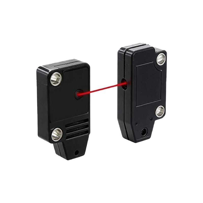
If the power supply checks are within specification, the investigation must shift to the sensor's load and operating environment. Disconnect the load (e.g., the ECU input, relay coil) from the sensor's output signal wire. If the power light stabilizes with the load disconnected, the issue lies in an overloaded or shorted load circuit. Use the multimeter to check the load's resistance and for any short to ground or battery positive. Furthermore, environmental contamination can cause internal faults. Inspect the sensor lens for accumulation of dirt, oil, or debris that might be causing internal reflection errors, potentially confusing the logic circuit and triggering a fault condition indicated by the flashing power light.
Resolving Issues and Preventive Maintenance
Resolution depends on the root cause identified. For power supply issues, repair or replace faulty wiring, connectors, or the power source itself. Installing a dedicated voltage regulator or noise suppression filter may be necessary in electrically noisy environments. For load-related problems, ensure the connected device's input impedance matches the sensor's output specifications and repair any shorts. Clean the sensor lens meticulously with appropriate solvents. As a preventive measure, establish regular inspection schedules for wiring integrity and connector seals. Ensure sensors are selected with an appropriate IP rating for their location and that installation follows best practices for strain relief and protection from physical damage and environmental contaminants.