Introduction to Photoelectric Sensors
Photoelectric sensors are indispensable components in modern industrial automation, renowned for their non-contact detection capabilities. These devices operate by emitting a beam of light, typically from an LED or laser diode, and detecting changes in the received light intensity to sense the presence, absence, or position of an object. Their applications span across manufacturing lines, packaging systems, material handling, and safety equipment, offering high precision, reliability, and versatility. Unlike mechanical switches, photoelectric sensors provide rapid response times and minimal wear, making them ideal for high-speed operations and harsh environments. Understanding their fundamental working principle is crucial for engineers and technicians to optimize system performance and troubleshoot issues effectively. This article delves into the core mechanisms, supported by clear diagrams, to demystify how these sensors function in practical scenarios.
Core Components and Light Sources
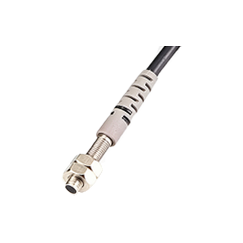
At the heart of every photoelectric sensor are three primary components: an emitter, a receiver, and a signal processing unit. The emitter generates the light beam, which can be visible red, infrared, or laser light, depending on the application requirements. Infrared is commonly used for its immunity to ambient light interference, while laser sources offer focused beams for long-range or precise detection. The receiver, typically a phototransistor or photodiode, captures the light and converts it into an electrical signal. The signal processing unit then analyzes this signal, comparing it to a preset threshold to determine the sensor's output state. Key parameters include sensing distance, response time, and light source wavelength, which influence the sensor's suitability for specific tasks. Diagrams illustrating these components help visualize the internal architecture and their interconnections, forming the basis for the various operating modes.
Through-Beam Sensing Mode
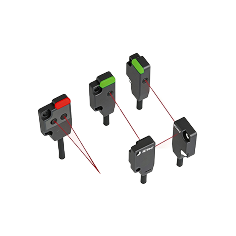
The through-beam (or opposed) mode is one of the most reliable and long-range photoelectric sensing methods. In this configuration, the emitter and receiver are housed in separate units, positioned directly opposite each other. The emitter projects a continuous light beam toward the receiver. When an object interrupts this beam, the receiver detects a drop in light intensity, triggering an output signal. This mode is highly effective for detecting opaque objects over distances up to several meters, with strong immunity to environmental factors like dust or color variations. However, it requires precise alignment of the two units, which can be challenging in dynamic setups. A diagram of this mode typically shows the emitter and receiver on either side of a conveyor, with the beam path clearly marked, highlighting the interruption point where detection occurs.
Retroreflective Sensing Mode
Retroreflective sensors combine the emitter and receiver into a single housing, simplifying installation. They work by directing light toward a retroreflector, such as a prismatic tape or mirror, which reflects the beam back to the receiver. When an object breaks the reflected beam, the sensor activates. This mode offers a good balance between range and convenience, suitable for medium-distance applications. A critical consideration is the potential for false triggers from shiny objects that might reflect light similarly to the reflector; polarized filters are often used to mitigate this by allowing only light with a specific polarization to be detected. Diagrams for retroreflective mode illustrate the integrated sensor unit, the reflector's position, and the triangular light path, emphasizing how the beam returns along the same axis.
Diffuse Reflective Sensing Mode
Diffuse (or proximity) mode sensors also integrate the emitter and receiver but do not require a separate reflector. Instead, they rely on the light diffusing off the target object's surface. The emitter sends out light, and if an object is within the sensing range, some of that light scatters back to the receiver. This mode is ideal for detecting objects at close ranges and is easy to install since only one unit is needed. However, performance can be affected by the object's color, texture, and reflectivity—lighter colors typically provide longer sensing distances than dark ones. Background suppression techniques, using triangulation principles, help by focusing detection on a specific distance zone, ignoring objects beyond it. A diffuse mode diagram often shows the sensor emitting a cone of light, with the receiver picking up reflections from a nearby object, while more distant surfaces are ignored.
Signal Processing and Output Types
Once the receiver converts light into an electrical current, the signal processing unit takes over. This circuitry amplifies the weak signal, filters out noise from ambient light or electrical interference, and compares it to a threshold level set during calibration. Based on this comparison, the sensor generates an output signal, which can be digital (e.g., NPN/PNP transistor switches) or analog (e.g., 4-20 mA or 0-10 V proportional to distance). Some advanced sensors feature programmable logic functions or IO-Link communication for real-time data exchange. Timing functions, like on-delay or off-delay, add flexibility for control applications. Diagrams here might depict a block diagram of the signal chain, from light reception to output switching, illustrating how external factors are mitigated to ensure stable operation.
Application Examples and Selection Criteria
Photoelectric sensors are deployed in diverse settings, such as counting bottles on a production line, detecting labels on packaging, or ensuring safety in automated machinery. For instance, through-beam sensors might guard a hazardous area, while diffuse sensors could verify part presence in an assembly robot. When selecting a sensor, engineers must consider factors like sensing distance, object size, material, environmental conditions (e.g., temperature, humidity, contaminants), and required response speed. Diagrams in application contexts show sensors integrated into systems, with annotations explaining their role—for example, a sensor positioned to detect a workpiece on a conveyor, triggering a robotic arm. Proper selection ensures reliability and reduces downtime, making it a critical step in design.
Maintenance and Troubleshooting Tips
To maintain optimal performance, regular cleaning of lenses and reflectors is essential, as dirt accumulation can attenuate light beams. Alignment checks are crucial for through-beam and retroreflective types, using alignment indicators or built-in diagnostics. Common issues include false triggers from reflective backgrounds or insufficient signal strength, often resolved by adjusting sensitivity settings or repositioning the sensor. LED status lights on sensors provide visual feedback for troubleshooting. A troubleshooting diagram might flowchart potential problems—like no output or erratic behavior—and guide users through steps like checking power supply, inspecting for obstructions, or verifying wiring connections. Preventive maintenance schedules help extend sensor lifespan and ensure consistent operation in demanding industrial environments.