Understanding the Core Principle
Infrared (IR) proximity sensors operate on a straightforward principle: they emit an infrared light beam and measure the intensity of the light that is reflected back to a receiver. The core component is typically an IR LED for emission and a photodiode or phototransistor for reception. The key parameter, detection distance, is not a fixed value but a range determined by the sensor's output signal crossing a predefined threshold. This distance is fundamentally governed by the inverse-square law of light propagation; the intensity of reflected light decreases with the square of the distance to the target. Therefore, the sensor's sensitivity and the emitter's power are primary design levers for defining the operational range.
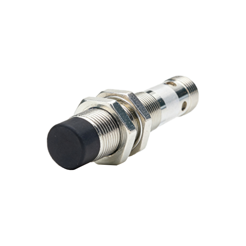
Primary Factors Influencing Detection Range
Several critical factors directly impact the maximum and reliable detection distance of an IR proximity sensor. First, the output power of the IR emitter is paramount. A higher-power LED can project a stronger signal, enabling detection of objects at greater distances. Second, the sensitivity and signal-to-noise ratio of the receiver circuit determine how well it can distinguish the weak reflected signal from ambient electrical and optical noise. Third, the target's reflectivity, or albedo, is a major variable. A matte white surface reflects IR light much more effectively than a glossy black or transparent one, leading to significant variations in achievable range for the same sensor. Finally, environmental conditions, such as ambient IR light from sunlight or artificial sources, can saturate the receiver or create false signals, effectively reducing the usable range.
Optical Design and Component Selection
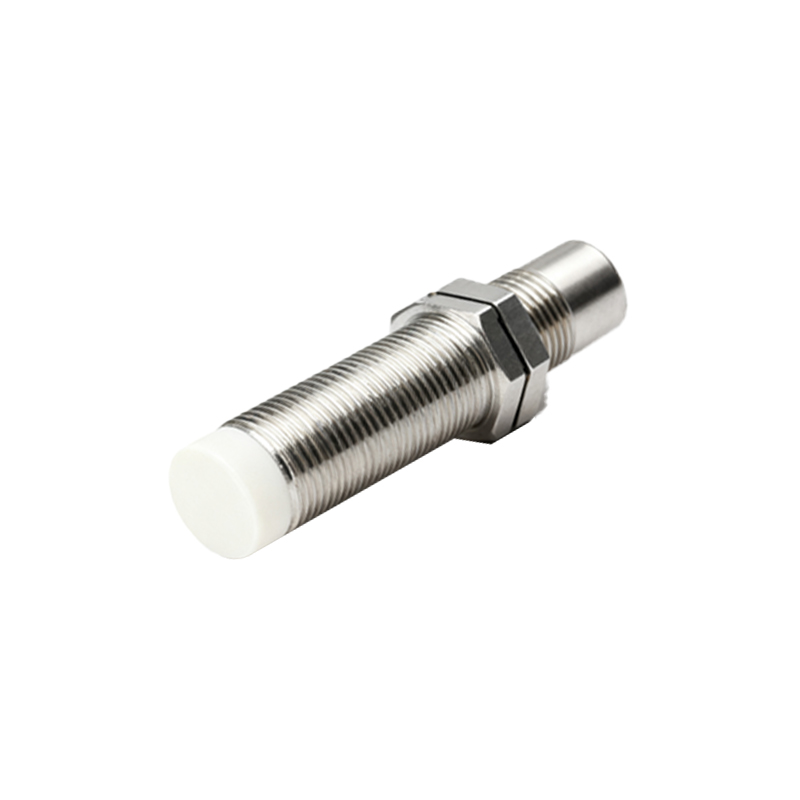
The physical design of the sensor package plays a crucial role. Lenses are often used to collimate the emitted IR beam into a focused, narrow path, increasing its intensity over distance and defining a precise detection field. Similarly, a lens on the receiver side can increase its effective collection area. The placement and optical barrier between the emitter and receiver are critical to minimize direct crosstalk (light leaking directly from LED to photodiode without reflection), which sets a minimum detection distance. Engineers must select components with appropriate wavelength matching (typically 850nm or 940nm) and consider the viewing angles of both emitter and receiver to shape the sensor's field of view and distance profile.
Signal Processing and Circuitry for Enhanced Performance
Raw analog signals from the photodetector are susceptible to noise and interference. Advanced signal processing techniques are essential for maximizing stable detection distance. Modulating the IR emitter with a specific frequency (e.g., a 38kHz carrier) and tuning the receiver to respond only to that frequency effectively filters out constant ambient light. Using a transimpedance amplifier (TIA) to convert the photodiode's current into a voltage, followed by filtering and amplification stages, boosts the weak signal. Implementing automatic gain control (AGC) or adaptive threshold algorithms can help maintain consistent performance across targets with different reflectivities, creating a more uniform perceived detection distance.
Calibration and Environmental Compensation
To ensure accuracy and repeatability in real-world applications, calibration is mandatory. This involves characterizing the sensor's response curve against known distances and target materials. Temperature compensation is also vital, as the output of both IR LEDs and photodiodes drifts with temperature changes, which can falsely indicate a change in distance. Some integrated sensor modules include digital interfaces (I2C, UART) and on-chip processing that handle internal calibration, temperature compensation, and provide a direct digital distance reading, simplifying system integration and improving reliability across operating conditions.
Practical Optimization Strategies
Optimizing for a specific detection distance requires a systematic approach. Begin by clearly defining the target material, required range, and environmental constraints. Select an emitter with sufficient optical power and pair it with a high-sensitivity photodetector. Design the optics to achieve the desired beam pattern. Implement modulated emission with synchronous detection in the circuitry to reject noise. Shield the sensor from stray light and electrical noise sources on the PCB. Finally, develop a calibration routine for the end application, possibly storing compensation coefficients in non-volatile memory. Testing under worst-case scenarios (e.g., low-reflectivity target, high ambient light) is essential to validate the robust operational distance.
Common Applications and Distance Requirements
IR proximity sensors are ubiquitous, each with distinct distance needs. In mobile devices for screen blanking, the required range is very short, typically 1-10 cm, focusing on power efficiency and miniaturization. In robotic vacuum cleaners, sensors may need to detect obstacles at 10-30 cm to avoid collisions. Industrial automation uses them for object counting or position verification at ranges from a few centimeters up to a meter, demanding high reliability. Touchless faucets and dispens