Understanding the Fundamentals of Photoelectric Sensing
Photoelectric sensors operate on the principle of converting light signals into electrical signals. At their core, these devices consist of an emitter, which projects a light beam, and a receiver, which detects the presence or absence of that beam. The interaction between the emitted light and the target object forms the basis for detection. The key parameters governing this interaction include the wavelength of the emitted light, the intensity of the beam, and the optical characteristics of the target. Common light sources include LEDs, with red, infrared, and laser variants being predominant in industrial applications due to their coherence, longevity, and specific material interaction properties. The receiver, typically a phototransistor or photodiode, is tuned to respond to the emitter's specific wavelength, ensuring signal integrity and minimizing interference from ambient light. This fundamental emitter-receiver pairing is the starting point for all discussions on directionality, as the spatial relationship between these two components defines the sensor's operational envelope and detection logic.
The Critical Role of Directionality in Application Success
Directionality is not merely a technical specification; it is the defining factor for a sensor's suitability in a given application. It refers to the precise spatial path and angular spread of the emitted light beam and the corresponding field of view of the receiver. A sensor with high directionality features a narrow, well-collimated beam, ideal for detecting small objects, achieving long sensing ranges, or providing precise edge detection. Conversely, a sensor with a wider beam angle offers a larger detection area but at the cost of reduced range and potential susceptibility to background interference. Engineers must evaluate the required sensing distance, the size and positioning tolerance of the target, and the environmental conditions. For instance, aligning a highly directional thru-beam sensor across a conveyor requires precise mechanical mounting to ensure the beam hits the receiver. Failure to account for directionality can lead to false triggers, missed detections, or inconsistent performance, directly impacting production line efficiency and quality control.
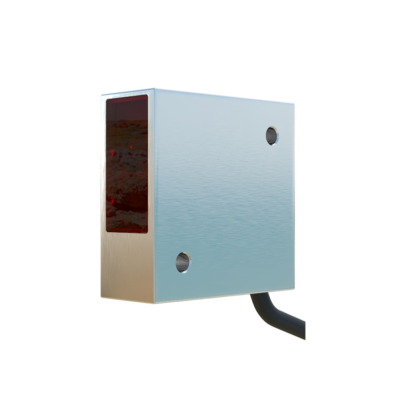
Comparing Sensing Modes: Through-Beam, Retroreflective, and Diffuse
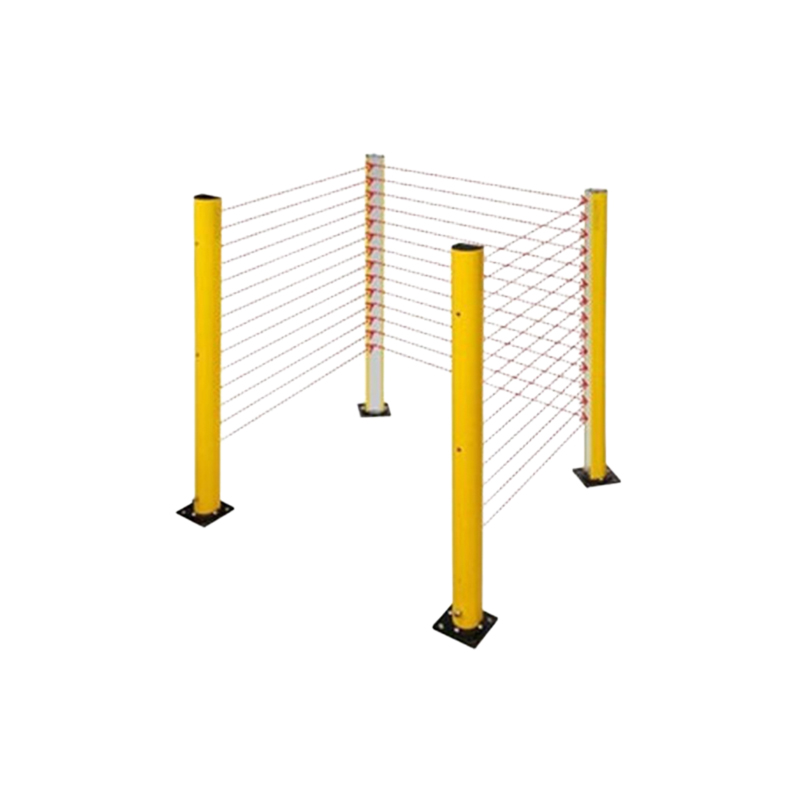
The directionality of a photoelectric sensor is intrinsically linked to its operating mode. The three primary modes offer distinct directional characteristics. Through-beam sensors, comprising separate emitter and receiver units, exhibit the highest directionality and longest range. The beam travels directly from emitter to receiver, creating a precise "light curtain." Detection occurs when an object interrupts this straight-line path. Retroreflective sensors house both emitter and receiver in a single housing, relying on a reflector to bounce the beam back. Their directionality is high but slightly less than through-beam due to the reflective path alignment tolerance. Diffuse (proximity) sensors, with co-located emitter and receiver, detect light reflected directly off the target. This mode has the lowest inherent directionality, as detection depends on the target's reflectivity, color, and surface angle relative to the sensor. The choice of mode is a direct trade-off between installation complexity, required precision, and environmental constraints, with directionality being the central differentiator.
Beam Patterns and Their Impact on Detection Accuracy
Beyond the basic mode, the emitted beam's pattern—shaped by lenses and apertures—further refines directionality. Common patterns include spot, rectangular, and focused linear beams. A precise spot beam, often from a laser diode source, provides exceptional directionality for detecting minute objects or performing exact positioning. Rectangular or slit beams are used in edge guidance or web break detection, where directionality is controlled in one axis more than the other. The receiver's field of view must be appropriately matched to this beam pattern. A mismatch can cause instability; for example, a very narrow beam with a very wide receiver field of view may detect stray reflections. Data sheets specify beam diagrams and displacement characteristics, showing the allowable lateral or vertical misalignment before signal loss. Understanding these diagrams is crucial for designing robust mounting fixtures and ensuring reliable operation despite machine vibration or thermal drift.
Environmental Factors Influencing Directional Performance
The operational environment can significantly degrade the designed directionality of a sensor. Airborne contaminants like dust, steam, or oil mist can scatter the light beam, causing attenuation or false reflections that effectively broaden or bend the perceived beam path. Intense ambient light from welding arcs, furnaces, or sunlight can flood the receiver, reducing the signal-to-noise ratio and effectively "blinding" it to its specific directional signal. To combat this, engineers employ several strategies. Using sensors with modulated LED light and tuned receiving circuits helps ignore constant ambient light. For highly directional sensors in dirty environments, physical air purge kits or protective shrouds can keep the lens clean. Selecting a specific light wavelength, such as green light for red plastic detection or infrared for general purpose, can also improve performance by minimizing environmental absorption or reflection. The choice of housing material (e.g., metal vs. plastic) and ingress protection (IP) rating also contributes to maintaining long-term directional integrity.
Advanced Features for Enhanced Directional Control
Modern photoelectric sensors incorporate sophisticated features that provide engineers with unprecedented control over directionality. Background suppression technology, using triangulation or timed pulse principles, allows a diffuse sensor to ignore objects beyond a set distance, effectively creating a sharp, invisible sensing plane at a specific point. This mimics high directionality without requiring a reflector. Polarizing filters are used with retroreflective sensors to ignore reflections from shiny, flat surfaces (like metal or plastic), ensuring detection only occurs when the beam returns from the intended, polarized reflector. Fiber optic sensing units represent the ultimate in flexible directionality control; the sensing head can be extremely small and the fiber cable can be bent to route light precisely to or from hard-to-reach locations, separating the sensitive electronics from harsh environments. These advanced features solve complex application challenges where standard directional behavior is insufficient.
Practical Installation and Alignment Guidelines
Achieving the theoretical directionality promised by a data sheet requires meticulous installation. For through-beam and retroreflective systems, initial coarse alignment is often followed by fine-tuning using the sensor's alignment indicator (typically an LED or digital signal strength display). Mounting the sensor on a stable, vibration-resistant platform is essential. For critical, long-range applications, laser sighting tools or built-in visible red laser beams (even on infrared sensors) are invaluable for precise initial targeting. When aligning, consider potential targets of different sizes and ensure the beam's narrowest point (the "beam waist") is positioned at the expected detection point. Allow for thermal expansion of machinery over time, which may shift alignment. For diffuse sensors, understanding the effective beam angle is key; the sensor should be mounted so the target passes well within this cone at the expected distance. Proper installation turns the principle of directionality into a reliable, real-world detection solution.