Understanding Two-Wire Proximity Sensors
Two-wire proximity sensors are fundamental components in industrial automation, valued for their simplicity and cost-effectiveness. Unlike three-wire or four-wire sensors, they require only two connections: one for power and one for the signal. These sensors operate by modulating their internal current draw to indicate the detection state. Typically, they draw a low "quiescent" current when no target is present and a higher "switching" current when a target is detected. This current-based signaling method makes them inherently compatible with standard PLC digital input modules, which are designed to sense a current range. Common types include inductive sensors for metallic objects and capacitive sensors for non-metallic materials. Their two-wire design reduces wiring complexity and installation time, making them a popular choice for high-volume or cost-sensitive applications.
PLC Digital Input Module Compatibility
Successful integration hinges on ensuring compatibility between the sensor's electrical characteristics and the PLC input module's specifications. Most modern PLC digital input (DI) modules are "sinking" or "sourcing" and can accept two-wire sensors. The key parameters to verify are the sensor's operating voltage range, off-state leakage current, and on-state voltage drop. The PLC module's specification sheet will list its required "ON" current (minimum current to register a logic 1) and maximum allowable leakage current (to prevent a false ON state). A two-wire sensor's off-state leakage current must be below the module's maximum leakage threshold. Conversely, the sensor's on-state current must exceed the module's minimum "ON" current requirement, even considering the sensor's internal voltage drop at full load. Mismatches here are the primary cause of malfunction, such as sensors failing to trigger or inputs remaining permanently active.
Wiring Configuration and Circuit Design
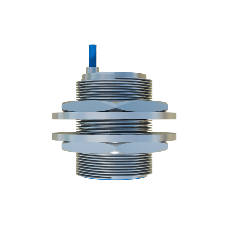
The wiring for a two-wire sensor to a PLC is straightforward but requires attention to polarity for DC sensors. For a DC sinking input module (common on the positive side), the typical configuration is: DC power supply positive connects to the sensor's brown wire; the sensor's blue wire connects to the PLC input terminal; and the PLC input's common (the sinking point) connects to the power supply negative. This forms a complete series circuit. It is critical to include a protective fuse or circuit breaker in the power line. For installations with multiple sensors, individual fusing is recommended. Always use shielded cable for long runs or in electrically noisy environments, connecting the shield to ground at the PLC end only to prevent ground loops. Proper wire sizing according to current and distance is essential to avoid voltage drop that could render the sensor inoperable.
Addressing Common Application Challenges
Several practical challenges can arise. A frequent issue is the residual leakage current of some two-wire sensors causing a PLC input to remain slightly energized in the "off" state. This can often be resolved by connecting a "bleeder" or "load resistor" in parallel with the PLC input. The resistor provides an alternative path for the leakage current, pulling the voltage at the input terminal below the PLC's OFF threshold. Another challenge is sensor inrush current during power-up, which can briefly exceed PLC input ratings. Selecting a PLC module with a robust inrush current tolerance or adding an inrush current limiter can mitigate this. In high-noise industrial settings, ensuring proper sensor mounting (especially for inductive types) and maintaining distance from power cables can prevent electromagnetic interference from causing erratic signals.
Diagnostics and Troubleshooting Techniques
Effective troubleshooting follows a logical sequence. First, verify power at the sensor using a multimeter. Check for the correct voltage between the brown (positive) and blue (wires). Next, measure the current in the circuit. In the off-state, it should equal the sensor's specified leakage current. When a target is presented, the current should jump to the specified on-state current. If the current does not change, the sensor may be faulty or incorrectly positioned. If the current changes correctly but the PLC does not register the change, the issue lies with the PLC input circuit or configuration. Most PLCs offer diagnostic data via software, such as input status and error codes, which should be consulted. A common oversight is forgetting to configure the input channel in the PLC programming software for the correct type (e.g., standard digital input versus fast counter input).
Best Practices for Reliable Operation
To ensure long-term reliability, adhere to several best practices. Always consult and cross-reference the datasheets of both the proximity sensor and the PLC input module before design and procurement. Implement a routine preventive maintenance schedule to clean sensor faces and check