Understanding the Communication Failure
A "No Communication" fault with a rear cover proximity sensor control unit is a critical diagnostic trouble code (DTC) prevalent in automated industrial machinery and modern vehicle body systems. This fault indicates a complete breakdown in data exchange between the sensor control module and the primary controller, such as a PLC or central ECU. The rear cover sensor is pivotal for safety interlocking, ensuring moving parts or access panels are securely closed before machine operation commences. When communication halts, it can trigger full system shutdowns, create production bottlenecks, or pose significant safety hazards. The root cause is rarely the sensor itself but lies within the communication pathway or the control unit's power and processing integrity.
Primary Diagnostic Steps and Voltage Checks
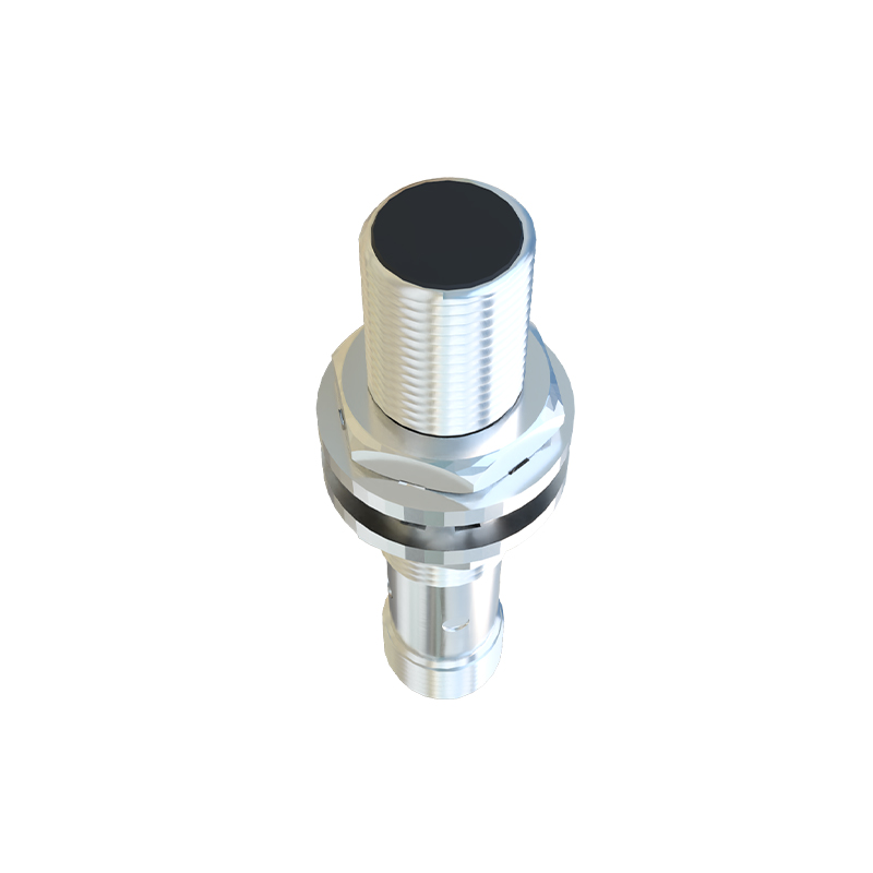
Initiate diagnostics by verifying the foundational requirements: power, ground, and network integrity. First, use a digital multimeter (DMM) to check for battery voltage (typically 12V or 24V DC) at the control unit's designated power supply pin with the harness connected. A low or absent voltage points to a blown fuse, corroded wiring, or a faulty relay. Next, confirm a clean ground connection by measuring resistance between the unit's ground pin and the chassis; it should be near zero ohms. Simultaneously, inspect the physical harness and connectors for damage, corrosion, or loose pins, which are frequent culprits in vibration-prone environments near rear covers.
Network Integrity and CAN Bus Specifics
Most modern proximity sensor control units communicate via CAN (Controller Area Network) bus. A loss of communication often stems from network issues. Probe the CAN High (CAN_H) and CAN Low (CAN_L) lines at the unit's connector. With the system powered, you should measure an average voltage of approximately 2.5V on each line relative to ground, with CAN_H slightly higher and CAN_L slightly lower. Identical voltages or a reading of 0V indicate a short or break. Use an oscilloscope for a definitive view; a healthy CAN signal shows two complementary, mirrored waveforms. A missing or distorted waveform confirms network failure, potentially caused by a termination resistor fault, a short to power/ground, or failure of another node on the same bus segment.
Control Unit Internal Failure Analysis
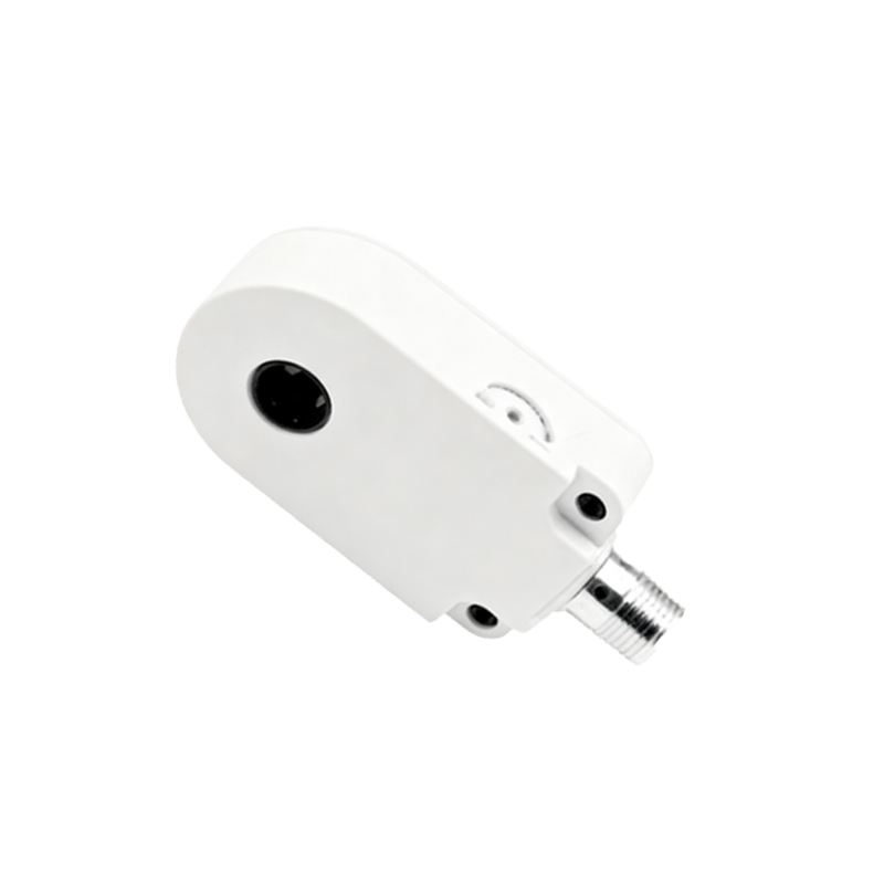
If power, ground, and network signals are confirmed present and correct, the fault likely resides within the control unit itself. Internal failures can include a damaged transceiver IC, a corrupted microprocessor, or failed voltage regulators. These are often precipitated by voltage spikes, moisture ingress, or extreme thermal cycling. While component-level repair is seldom feasible in the field, a conclusive test is to substitute the unit with a known-good module. If communication is restored immediately with the replacement, the original control unit is defective. Always ensure the replacement unit's part number and software calibration are identical to avoid compatibility issues.
Software and Configuration Considerations
Do not overlook software glitches or configuration errors. A control unit may appear electrically sound but remain unresponsive due to corrupted firmware or an incorrect parameter setting. Attempt to re-flash the unit's firmware using the manufacturer's proprietary diagnostic software and programming interface. Check for related DTCs in the main controller that may indicate a configuration mismatch, such as an incorrect node address or baud rate setting programmed for the network. In systems with multiple modules, a fault in one can sometimes cause the entire bus to go silent, making it appear as if the sensor unit has failed.
Preventive Maintenance and Best Practices
Preventing communication failures involves a regimented maintenance schedule. Regularly inspect and clean all electrical connections associated with rear cover sensors, applying dielectric grease to deter corrosion. Secure wiring harnesses away from heat sources and moving parts to prevent abrasion. Implement surge protection devices on power lines feeding sensitive control units. During system modifications or expansions, ensure network loading and termination resistance calculations are adhered to strictly. Finally, maintain a log of all communication faults; recurring issues in a specific area often point to a systemic design flaw or environmental challenge requiring an engineering solution.