Introduction to U-Shaped Slot Photoelectric Sensors
U-shaped slot photoelectric sensors, often referred to as through-beam sensors with a built-in gap, are widely utilized in industrial automation for object detection, counting, and positioning. These sensors consist of two main components housed in a single U-shaped body: an emitter and a receiver facing each other across a precise gap. When an object passes through this slot, it interrupts the light beam, triggering a switching output. Their compact, integrated design simplifies installation compared to separate emitter-receiver pairs, making them ideal for applications with space constraints or where alignment is challenging. Common models include diffuse-reflective and through-beam variants, with the latter offering higher accuracy and longer sensing distances. Understanding their electrical characteristics is crucial before proceeding with wiring, as they are available in both AC and DC voltage versions, along with NPN (sinking) or PNP (sourcing) output configurations.
Key Wiring Components and Safety Precautions
Before initiating any wiring procedure, ensure all power sources are disconnected to prevent electrical shock or equipment damage. Essential components include the sensor itself, a compatible power supply (matching voltage and current ratings, typically 12-24V DC or 90-250V AC), load devices (such as PLC input modules, relays, or indicators), and appropriate cables. Always refer to the manufacturer's datasheet for specific terminal designations, which generally include V+ (power supply positive), V- (power supply negative or ground), and OUT (output signal). Use shielded cables in electrically noisy environments to minimize interference, and secure all connections with proper terminals to avoid loose wires. Verify that the load current does not exceed the sensor's maximum switching capacity, usually stated in milliamps for DC models. Implementing a separate grounding point for the sensor chassis can further enhance stability and safety in industrial settings.
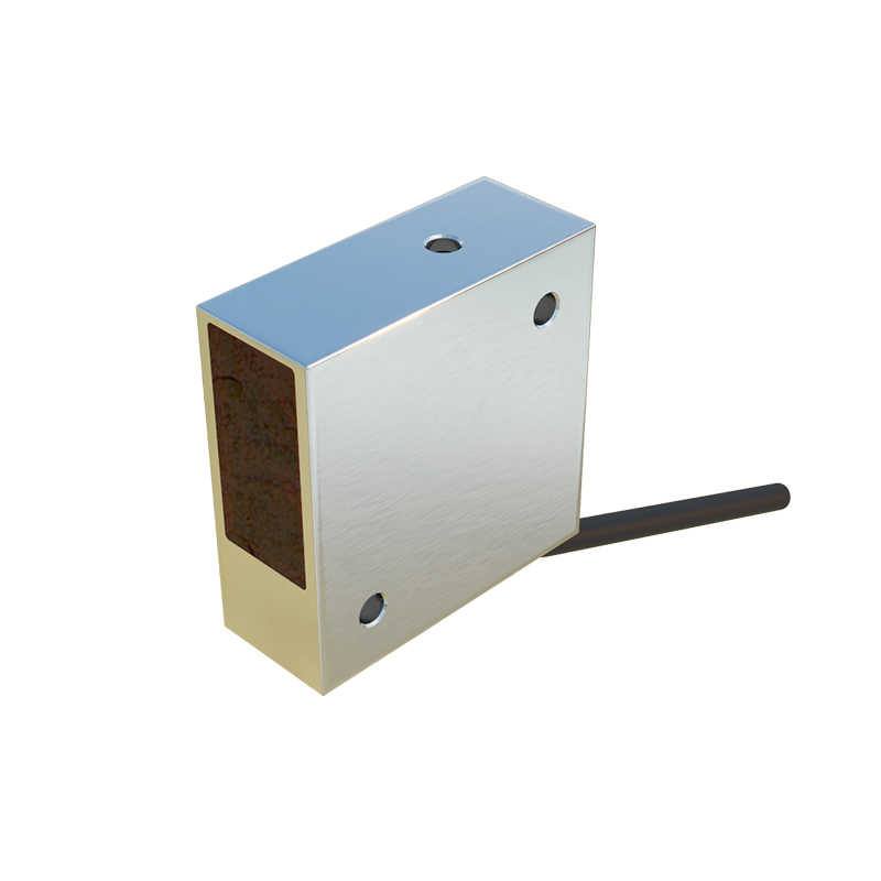
Step-by-Step Wiring Procedure for DC Models
For a standard 3-wire DC U-shaped slot sensor, begin by connecting the brown wire (typically V+) to the positive terminal of your DC power supply. Connect the blue wire (typically V- or 0V) to the negative terminal of the power supply. The remaining wire, often black or white, is the output (OUT) line. For a PNP (sourcing) sensor, this output provides positive voltage to the load when activated; connect it to one terminal of your load device (e.g., a PLC digital input). The other terminal of the load should then be connected to the power supply's negative (blue wire) line. For an NPN (sinking) sensor, the output sinks current to ground when active; connect the load between the positive supply (brown wire) and the sensor's output wire. Always install an in-line fuse on the power supply line for overload protection. After connections are made, power the system and test by passing an object through the sensor slot; the output LED should indicate state changes accordingly.
Wiring Configurations for AC and 4-Wire Sensors
AC-powered U-shaped slot sensors usually have two wires for power (often brown and blue) and a separate output wire. Connect the brown wire to the live (L) AC terminal and the blue wire to the neutral (N) terminal, ensuring correct voltage matching (e.g., 110V AC or 230V AC). The output wire, frequently black, connects to one side of the load, with the other load terminal linked to the neutral line. Some AC models include a relay contact output, allowing direct switching of higher loads. For 4-wire sensors, which provide both normally open (NO) and normally closed (NC) outputs, identify the additional output terminal from the datasheet. Typically, black is NO, white is NC, and they share common power connections. This configuration enables flexible control logic, such as fail-safe operations where the NC output remains active until an object interrupts the beam. In all cases, ensure proper insulation and use conduit or cable ducts in harsh industrial environments to protect against dust, moisture, and mechanical stress.
Troubleshooting Common Wiring Issues
If the sensor fails to operate after wiring, first check the power supply voltage with a multimeter to confirm it matches the sensor's requirements. Inspect all connections for looseness or incorrect polarity, especially for DC sensors where reversed polarity can cause permanent damage. Verify that the load impedance is within specifications; an overload may cause the output to malfunction. Inconsistent detection may stem from environmental factors like strong ambient light interfering with the infrared beam—consider using sensors with modulated light or installing protective shrouds. Electrical noise from nearby motors or frequency inverters can induce false triggering; reroute sensor cables away from high-power lines and ensure proper shielding grounding. If the output LED lights but the load does not respond, test the load directly with an external power source to rule out sensor failure. Regularly clean the sensor's optical windows from dust or debris, as contamination can attenuate the light beam and reduce sensing reliability.
Best Practices for Installation and Maintenance
To maximize performance and longevity, mount the U-shaped slot sensor securely on a stable surface, aligning the slot perpendicular to the object's path. Ensure the target object fully interrupts the beam and is within the specified size and material limits; transparent or highly reflective objects may require specialized sensors. Maintain the recommended gap between the sensor and moving parts to avoid physical damage. For long-term operation, implement periodic inspection schedules to verify wiring integrity, clean optical components, and test response times. In conveyor or packaging systems, consider using sensors with built-in timers or logic functions to filter out vibrations or transient interruptions. Document the wiring diagram and sensor parameters for future maintenance, and always keep spare sensors on hand for critical applications to minimize downtime. By adhering to these guidelines, engineers can ensure reliable and efficient integration of U-shaped slot photoelectric sensors into diverse industrial automation projects.