Proximity sensors have become integral components in modern automation, consumer electronics, and industrial systems. While the sensor itself detects the presence or absence of an object, its true utility is unlocked only through a well-designed subsequent interface circuit. This circuit, often referred to as the signal conditioning or processing stage, is critical for transforming the raw sensor output into a reliable, accurate, and usable signal for a microcontroller or logic system.
The primary function of the subsequent circuit is to bridge the gap between the sensor's analog or digital output and the requirements of the system's control unit. For analog output sensors, such as inductive, capacitive, or infrared types, the initial stage typically involves amplification. A raw analog signal is often weak and susceptible to noise. An operational amplifier (op-amp) configured in a non-inverting or instrumentation amplifier topology is commonly employed to boost the signal to a suitable voltage level, typically matching the analog-to-digital converter (ADC) input range of a microcontroller, like 0-3.3V or 0-5V.
Following amplification, filtering is almost always necessary. Industrial environments are rife with electromagnetic interference (EMI), and even consumer devices face noise from power supplies and digital circuits. A low-pass filter is standard to attenuate high-frequency noise that does not correspond to the actual proximity detection event. The cutoff frequency is chosen based on the sensor's response speed and the application's requirements. For instance, a slow-moving conveyor system requires a different filter design than a high-speed object counting application.
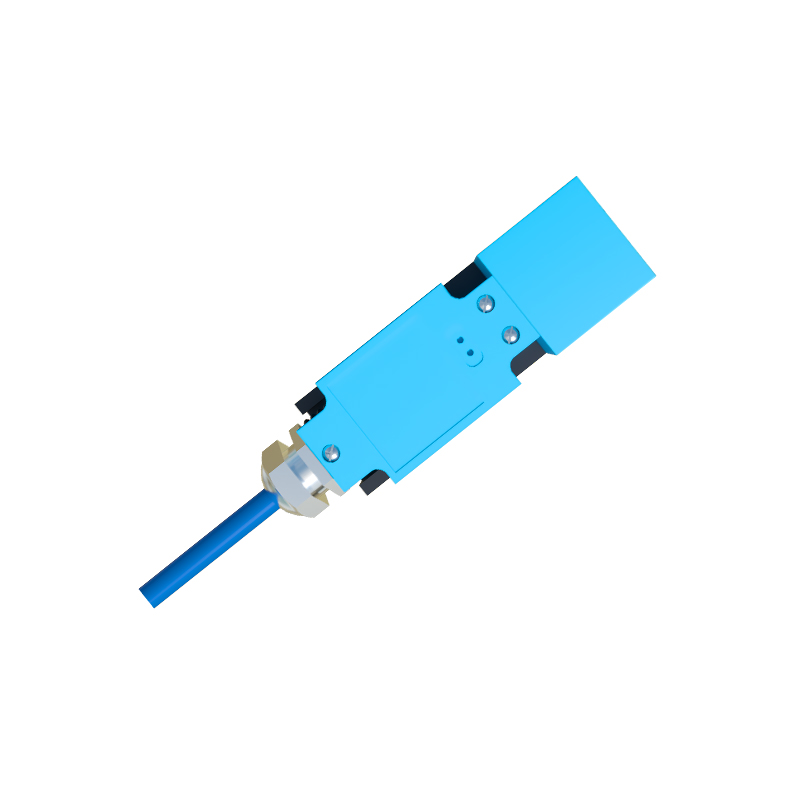
For digital output sensors, which provide a simple high/low logic signal, the subsequent circuit focuses on signal integrity and interfacing. A common requirement is a pull-up or pull-down resistor to ensure a defined logic level when the sensor's output is in a high-impedance state. Schmitt trigger buffers or dedicated logic level translators are frequently used to condition the digital signal, providing hysteresis to prevent oscillation near the threshold voltage and ensuring compatibility between different voltage domains (e.g., a 5V sensor output to a 3.3V microcontroller input).
Power management is another crucial aspect. Many proximity sensors require stable, clean power supplies. Voltage regulators and decoupling capacitors (both bulk and ceramic) must be placed close to the sensor's power pins to minimize noise injection and voltage fluctuations. For battery-powered devices, considerations for low quiescent current in the regulator and the entire signal chain become paramount to extend operational life.
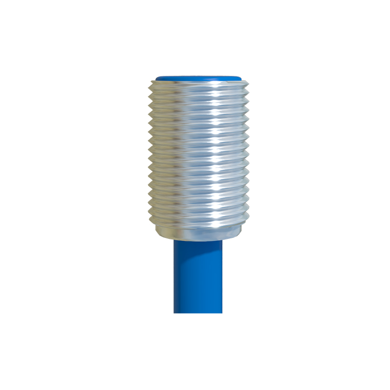
In more advanced implementations, the subsequent circuit may include additional features. A window comparator can be used to create an operational zone, triggering an output only when the object is within a specific distance range. For multiplexing multiple sensors, analog multiplexers or digital addressable interfaces (like I2C or SPI) are incorporated into the circuit design to reduce wiring and microcontroller pin count.
Protection circuits are non-negotiable in harsh environments. Transient voltage suppressors (TVS diodes) protect against voltage spikes on both power and signal lines. Series resistors can limit current in case of faults. For sensors in washdown or outdoor applications, conformal coating on the PCB may be part of the overall circuit protection strategy.
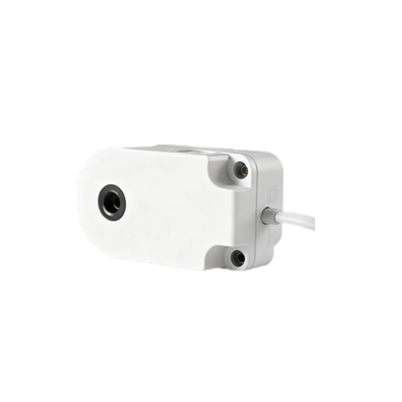
Finally, the design must be validated through prototyping and testing. Key parameters to verify include sensitivity, repeatability, response time, and immunity to environmental factors like temperature drift or ambient light (for optical sensors). Using a programmable load and an oscilloscope to observe the circuit's behavior under various conditions is standard practice.
In summary, the subsequent circuit for a proximity sensor is a tailored system that conditions, protects, and interfaces the sensor's output. Its design demands a careful balance of analog and digital electronics principles, an understanding of the operational environment, and a clear definition of the system-level requirements. A robust interface circuit ensures that the precision and capability of the proximity sensor are fully realized in the final application.