Introduction to Buduke Photoelectric Sensors
Buduke photoelectric sensors are widely recognized in industrial automation for their reliability, precision, and versatility. These sensors operate by emitting a light beam, typically infrared, visible red, or laser, and detecting changes in the received light to sense the presence, absence, or distance of an object. Common types include through-beam, retro-reflective, and diffuse reflective sensors, each suited for specific applications ranging from object detection on conveyor belts to position sensing in machinery. Understanding the correct wiring configuration is fundamental to ensuring optimal performance, safety, and integration with control systems such as PLCs (Programmable Logic Controllers). This guide provides a detailed overview of standard wiring diagrams for Buduke photoelectric sensors, adhering to industry norms and electrical standards.
Key Components and Terminal Identification
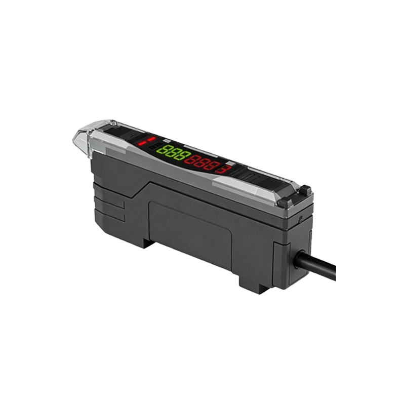
A typical Buduke photoelectric sensor housing features clearly marked terminals or a connector for wiring. The standard configuration often includes three or four wires, though some advanced models may have more for additional functions. For a basic 3-wire DC sensor, the terminals are commonly labeled as: Brown wire for positive supply voltage (V+ or +V), Blue wire for negative supply or common ground (V- or 0V), and Black wire for the output signal (OUT or NO/NC). Some models include a White wire for complementary output or function selection. It is crucial to consult the specific sensor's datasheet, as wire colors and functions can vary by model and output type (NPN sinking or PNP sourcing). Proper identification prevents incorrect connections that could lead to sensor damage or system malfunction.
Standard Wiring Diagram for DC 3-Wire Sensors
The DC 3-wire sensor is the most prevalent in industrial settings. For an NPN output type (sinking output), the wiring is as follows: Connect the Brown wire to the positive terminal of the DC power supply (typically +12V to +24V DC). Connect the Blue wire to the negative terminal of the power supply (0V DC). The Black output wire is connected to the load (e.g., a PLC input module, relay coil, or indicator lamp), and the other side of the load is then connected to the positive supply voltage. When the sensor is activated, the NPN transistor switches, connecting the Black wire to 0V (sinking current), thus completing the circuit to energize the load. For a PNP output type (sourcing output), the Brown and Blue wires are connected similarly. However, the Black output wire connects to the load, and the other side of the load is connected to the negative supply (0V). When activated, the PNP transistor sources current from V+ through the load to 0V. Always ensure the power supply voltage matches the sensor's rated voltage.
Wiring for 4-Wire and Special Function Sensors
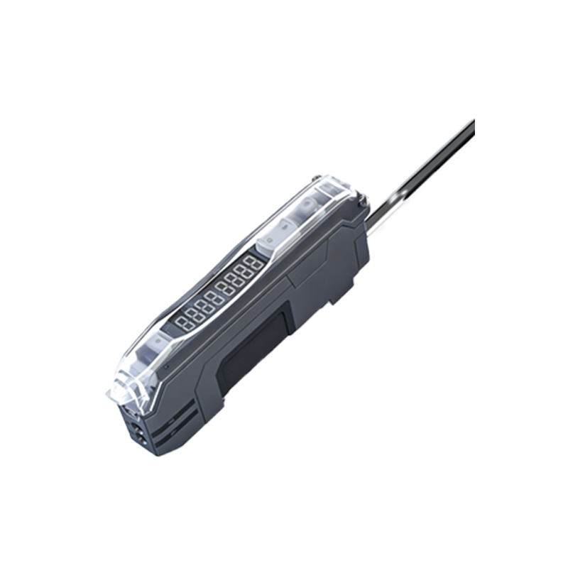
Buduke also offers 4-wire sensors, which often provide both a Normally Open (NO) and a Normally Closed (NC) output, or include a separate wire for an output status indicator or mode selection. In a common 4-wire DC configuration, wires may be: Brown (V+), Blue (V-), Black (NO output), and White (NC output). To wire such a sensor, connect the Brown and Blue to the power supply. The Black wire can be used as the primary signal wire to a PLC input, while the White wire can be connected to a different input for a complementary signal or safety interlock. Some sensors feature a teach-in function or sensitivity adjustment via a separate wire or built-in potentiometer; wiring for these functions should follow the manufacturer's instructions precisely to enable programming or calibration without disassembly.
Connection to Programmable Logic Controllers (PLCs)
Integrating a Buduke photoelectric sensor with a PLC is a common practice. For an NPN sensor connected to a sinking input PLC module, wire the sensor's Black output to the PLC's input point (e.g., I0.0). The positive side of the PLC input's internal circuit is usually connected to +24V DC, and the sensor acts as the switching path to 0V. For a PNP sensor connected to a sourcing input PLC module, wire the Black output to the PLC input point, with the PLC input's common connected to 0V. Always verify the PLC input type (sinking or sourcing) to ensure compatibility with the sensor's output. Proper shielding and grounding of cables are recommended to minimize electrical noise interference, especially in environments with motors or variable frequency drives. Use conduit or shielded cables, and connect the shield to a solid earth ground at one end only.
Safety Precautions and Troubleshooting Tips
Before commencing any wiring work, disconnect all power sources and lock out/tag out equipment to prevent electrical shock or accidental activation. Use wires of appropriate gauge for the current rating and ensure all connections are secure to avoid voltage drops or arcing. Common issues post-installation include sensor not triggering, erratic behavior, or short circuit. First, confirm power supply polarity and voltage. Use a multimeter to check for correct voltage between Brown (+) and Blue (-) wires. Next, verify the output signal by measuring voltage between the Black wire and Blue wire while activating the sensor. For NPN, voltage should drop near 0V when active; for PNP, it should rise near supply voltage. Ensure the sensing object is within range, clean the lens, and check for ambient light interference. Consult the sensor's manual for LED indicator status codes, which aid in diagnosing problems like alignment errors or contamination.
Conclusion and Best Practices
Correct wiring of Buduke photoelectric sensors is critical for reliable operation in automated systems. Always refer to the official wiring diagram provided in the product documentation, as specifications may change. Plan the installation considering environmental factors such as temperature, humidity, and exposure to chemicals, selecting appropriate sensor housing ratings (e.g., IP67 for dust and water resistance). Regularly inspect connections and sensor alignment as part of preventive maintenance. By following these guidelines, engineers and technicians can ensure seamless integration, longevity, and accuracy of Buduke photoelectric sensors, thereby enhancing overall system productivity and safety. For complex applications, consider consulting with Buduke technical support or a certified automation specialist.