Introduction to Photoelectric Sensor Circuits
Photoelectric sensors are fundamental components in modern industrial automation, utilizing light beams to detect the presence, absence, or distance of objects. An electrical training program focused on these circuits equips engineers with the practical skills necessary for designing, installing, and troubleshooting these critical systems. This training bridges the gap between theoretical knowledge of optoelectronics and hands-on application in real-world electrical panels and control systems. Understanding the core principles of light emission, reception, and signal conditioning is the first step toward mastering photoelectric sensor integration in complex machinery, conveyor systems, and safety interlocks.
Core Components and Circuit Architecture
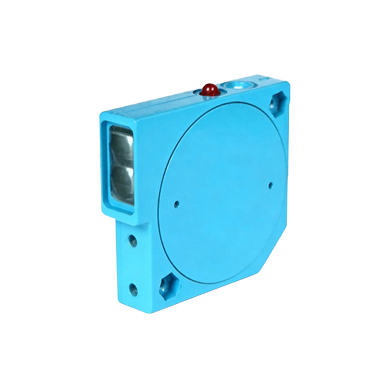
A standard photoelectric sensor circuit comprises several key components. The primary elements include the light emitter, typically a light-emitting diode (LED) for visible or infrared light, and the receiver, which is often a phototransistor or photodiode. The circuit also features a modulator/demodulator section to distinguish the sensor's light from ambient lighting, enhancing reliability. Furthermore, a signal amplifier and output switching stage (transistor or relay-based) are integral for converting the weak photocurrent into a robust, usable control signal. Trainees learn to identify these parts on datasheets and physically on devices, understanding how they interconnect on a printed circuit board (PCB) within the sensor housing and how they interface with external power supplies and programmable logic controllers (PLCs).
Wiring and Power Supply Considerations
Proper wiring is crucial for the safe and effective operation of photoelectric sensors. Training emphasizes the importance of voltage ratings, current requirements, and the distinction between sourcing (PNP) and sinking (NPN) output configurations. Engineers practice connecting sensors to direct current (DC) power sources, commonly 12-24V DC, while ensuring correct polarity. The curriculum covers shielding and routing of cables to minimize electrical noise interference, which can cause false triggering. Practical exercises involve using terminal blocks, DIN rail mounting, and implementing protective measures such as fuses and isolation to prevent damage from short circuits or voltage spikes in industrial environments.
Configuration and Alignment Techniques
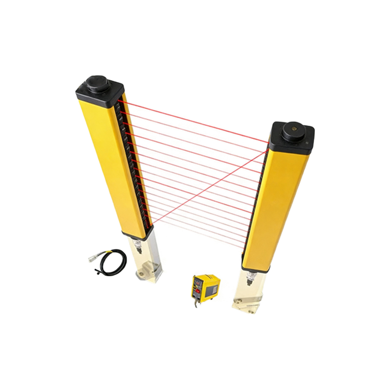
Once physically installed, photoelectric sensors require precise configuration and alignment. Training sessions provide hands-on experience with through-beam, retro-reflective, and diffuse reflection sensing modes. Engineers learn to use alignment tools and indicator LEDs to optimize the optical path. For adjustable sensors, trainees practice setting sensitivity thresholds (potentiometer or teach-in methods) to reliably detect target objects while ignoring background interference. This segment often involves simulating various target materials, colors, and surface finishes to understand their impact on reflectivity and sensor performance, a critical skill for application-specific tuning.
Integration with Control Systems
A photoelectric sensor is rarely an isolated device; it functions as an input to a larger control system. Training focuses on integrating the sensor's discrete output with PLCs, motor drives, and human-machine interfaces (HMIs). Engineers practice writing basic ladder logic or function block programs that use the sensor's signal to start/stop motors, count items, or trigger alarms. They learn to interpret input status on PLC modules and troubleshoot communication issues. This integration phase reinforces concepts of input/output (I/O) addressing, signal timing, and the development of simple automated sequences based on sensor feedback.
Diagnostic and Troubleshooting Procedures
Systematic troubleshooting is a core competency. Training develops a structured approach: verifying power supply integrity, checking for physical obstructions or lens contamination, and using multimeters to measure output voltage states under different conditions. Oscilloscopes may be introduced to examine the modulated light signal's quality. Common failure modes, such as degraded LED output, receiver failure, or misalignment due to vibration, are analyzed. Trainees work through fault scenarios, learning to distinguish between sensor faults, wiring faults, and controller programming errors, thereby reducing machine downtime in practical settings.
Safety Protocols and Standards Compliance
Working with electrical circuits and industrial equipment mandates strict adherence to safety standards. Training instills practices for lockout-tagout (LOTO) procedures when installing or servicing sensors connected to machinery. It covers relevant international standards, such as IEC 60947-5-2 for proximity sensors and general machine safety directives (e.g., ISO 13849). Emphasis is placed on using sensors in safety-critical applications, like light curtains for personnel protection, which require specialized knowledge of fail-safe design and periodic functional testing to ensure operational integrity and regulatory compliance.
Advanced Applications and Future Trends
Beyond basic detection, training explores advanced applications. This includes using analog output sensors for distance measurement, background suppression sensors for precise range-finding, and color recognition sensors. The curriculum may touch on the integration of smart sensors with Industrial Internet of Things (IIoT) networks, enabling predictive maintenance through self-diagnostics and data logging. Understanding these trends prepares engineers for the evolving landscape of Industry 4.0, where sensors become intelligent data points within a connected factory ecosystem, requiring skills in network configuration and data interpretation.
Conclusion and Skill Validation
Effective electrical training culminates in a comprehensive assessment of acquired skills. This typically involves a final practical project where trainees must design a small-scale detection system, select appropriate sensors, wire the circuit, integrate it with a controller, and successfully demonstrate its operation while documenting the process. Such validation ensures that engineers can confidently apply their knowledge to improve system reliability, efficiency, and innovation in their professional roles, solidifying photoelectric sensors as a vital tool in their electrical engineering expertise.