Understanding Capacitive Proximity Sensors
Capacitive proximity sensors are versatile devices used to detect both metallic and non-metallic objects, including liquids, powders, and granular materials. Their operation is based on the principle of capacitance change. The sensor forms one plate of a capacitor, with the target object acting as the other plate. When an object enters the sensor's electrostatic field, it alters the capacitance, triggering the sensor's output switch. This makes them ideal for applications where other sensor types, like inductive sensors, would fail, such as detecting plastic, glass, or liquid levels through a container wall. Their ability to sense through non-metallic barriers is a key advantage in many industrial automation and process control settings.
Key Components and Electrical Characteristics
A standard three-wire capacitive proximity sensor typically includes three primary terminals: Brown wire (L+ or +V), Blue wire (L- or 0V), and Black wire (Signal Output). Some models may also include a White wire for a complementary output or special function. These sensors are commonly available in both DC (10-30V DC) and AC (20-250V AC) variants. The load, such as a PLC input, relay, or indicator lamp, is connected between the output wire (Black) and the opposite supply terminal. It is crucial to consult the specific datasheet for voltage ratings, current sinking or sourcing configuration (NPN or PNP), and output types (normally open NO or normally closed NC) to ensure proper integration into the control circuit.
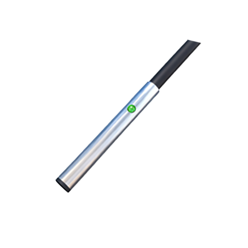
Standard DC Wiring Configuration Diagrams
For DC-powered sensors, two primary wiring schemes exist: PNP (sourcing) and NPN (sinking). In a PNP configuration, the Brown wire connects to the positive DC supply (+V), and the Blue wire connects to the common negative (0V). The Black output wire switches the positive voltage to the load. The load's other terminal is connected to 0V. Conversely, in an NPN configuration, the Brown wire connects to +V, and the Blue wire connects to 0V. Here, the Black output wire switches the 0V connection to the load, with the load's other terminal connected to +V. A detailed wiring diagram would show the power supply, sensor, and load in a complete loop, often including protective devices like fuses.
AC Sensor Wiring and Considerations
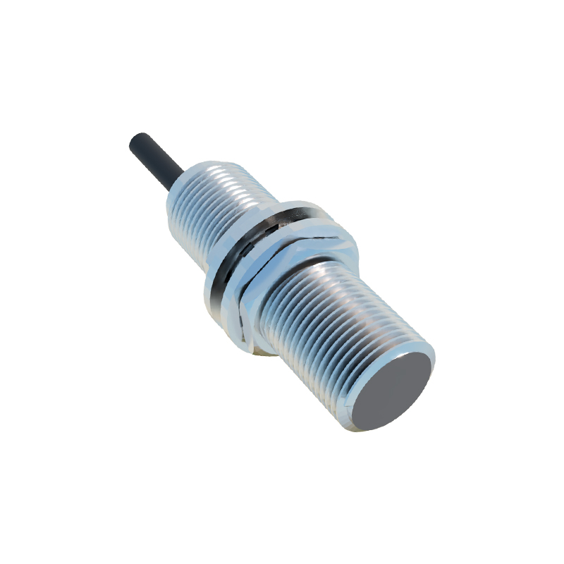
Wiring an AC capacitive proximity sensor involves connecting the Brown wire to the phase or line (L) terminal of the AC supply and the Blue wire to the neutral (N) terminal. The Black output wire is connected in series with the load, which is then connected back to the neutral line. AC sensors often have two-wire designs as well, where the sensor is connected in series with the load directly across the AC line. Special attention must be paid to leakage current in AC and DC two-wire sensors, as a residual current may flow even when the sensor is off, potentially causing false triggers with highly sensitive loads.
Shielded vs. Unshielded Sensor Mounting
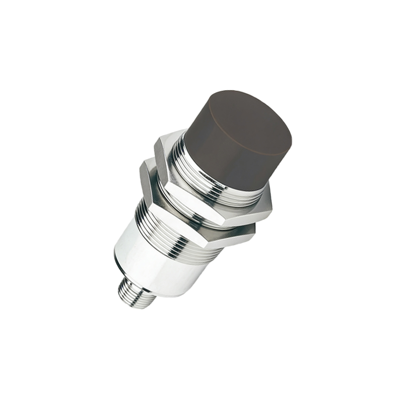
The physical installation significantly impacts performance. Capacitive sensors come in shielded (flush-mountable) and unshielded (non-flush mountable) designs. Shielded sensors can be mounted flush in metal without affecting their sensing field, making them suitable for tight spaces. Unshielded sensors have a larger, more extended sensing range but cannot be mounted flush with metal, as surrounding conductive material will disrupt the field. The wiring diagram does not change based on this, but the installation notes must specify the correct mounting style to achieve the advertised sensing distance and avoid interference from the mounting bracket or tank wall.
Practical Wiring Steps and Best Practices
First, always disconnect power before wiring. Identify the sensor type (DC/AC, PNP/NPN) from its label. Prepare the cables: strip the wire ends and use ferrules for a secure connection in terminal blocks. Connect the power supply wires (Brown and Blue) to the correct polarity and voltage. Connect the output wire (Black) to one terminal of the load device. Complete the circuit by connecting the load's other terminal to the opposite power supply rail. After connections are secure, apply power and test the sensor with a target object. Ensure all connections are tight, wires are routed away from high-voltage cables to prevent electrical noise, and the sensor face is clean for reliable operation.
Troubleshooting Common Wiring Issues
If the sensor fails to operate, check the power supply voltage with a multimeter at the sensor terminals. Verify the wiring against the diagram for the correct PNP/NPN configuration relative to the load. A common mistake is