Introduction to Bore Proximity Sensing
Proximity sensing within confined internal diameters, particularly bores as small as 3mm, presents a significant engineering challenge. These applications are common in precision manufacturing, medical devices, and miniature robotics, where monitoring the presence, position, or vibration of components inside a hollow shaft or housing is critical. The primary constraint is the severe spatial limitation, which dictates the sensor's physical size, sensing technology, and installation methodology. Selecting the wrong sensor can lead to unreliable detection, physical interference, or damage to both the sensor and the target. This guide delves into the technical considerations for reliably implementing proximity detection within a 3mm internal bore.
Sensor Technology Selection
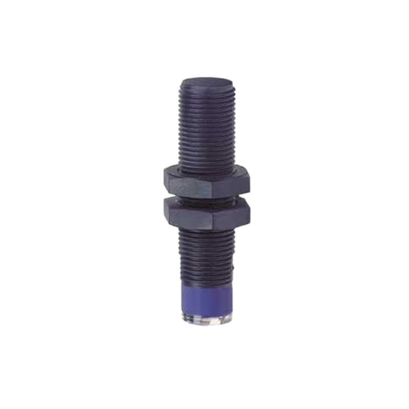
For a 3mm internal diameter, the choice of sensing technology is narrowed considerably. Inductive proximity sensors are often the preferred solution for detecting metallic targets within such a small bore. Their compact, cylindrical form factor can be designed to fit into tight spaces. However, the standard sensing range is typically a fraction of the sensor's face diameter. For a 3mm bore, a sensor with a body diameter of less than 2.5mm is required, which may offer an effective sensing distance of only 0.2mm to 0.5mm. This ultra-short range is a key specification. Capacitive sensors could be considered for non-metallic targets, but their sensitivity to environmental changes like humidity and their typically larger size relative to inductive types make them less ideal for this stringent application.
Key Design and Performance Parameters
Several parameters become paramount when specifying a sensor for a 3mm bore. First is the housing material and thread. Stainless steel (e.g., SUS303, SUS304) is standard for durability and chemical resistance. The sensor must be fully sealed (IP67 rating or higher) to withstand coolant, oil, or washdowns. Second, the switching frequency must be high enough for high-speed applications, such as counting teeth on a rotating micro-gear inside the bore. Third, temperature stability is crucial, as the confined space may lead to heat buildup. Finally, output configuration (PNP/NPN, analog, or IO-Link) must be compatible with the control system, with wiring that is appropriately thin and flexible to route out of the constrained area.
Installation and Alignment Challenges
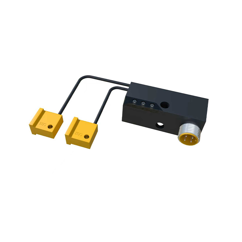
Precise mechanical installation is non-negotiable. The sensor must be securely mounted such that its sensing face is perfectly flush with, or recessed slightly from, the inner wall of the bore to avoid protrusion and damage. Any misalignment can drastically reduce the effective sensing distance. For through-hole mounting, a precision-machined thread or a custom mounting sleeve is essential. The minimal clearance also means that the target object's size, material, and approach path must be consistent. Variations in target surface finish or the presence of non-target metallic debris can cause false triggers. Careful consideration of the sensing axis relative to the target's movement is required.
Application-Specific Considerations
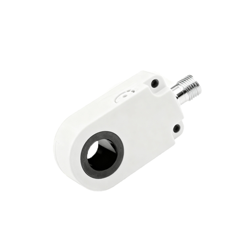
In practice, a 3mm bore sensing application often requires customization. For example, in a medical catheter assembly machine, a micro inductive sensor might verify the placement of a metallic stent inside a tube. In watchmaking, a sensor could detect the end-of-travel of a tiny axle within a gear train bore. In these scenarios, the sensor's electrical noise immunity is critical, as other high-frequency equipment may be nearby. Furthermore, the lead time and availability of such specialized, miniature sensors can be a project factor. Engineers must often collaborate closely with sensor manufacturers to develop a solution that meets the exact mechanical, electrical, and performance requirements.
Testing and Validation Protocol
Rigorous testing under actual or simulated operating conditions is the final step. This involves verifying the repeat accuracy of detection at the specified 3mm air gap (or less). Endurance testing should account for millions of operating cycles to ensure longevity. The test should also validate performance across the required temperature range and in the presence of expected contaminants like cutting fluid or metallic dust. Data logging the sensor's output signal over time can help identify any drift or intermittent behavior. A successful validation confirms that the chosen sensor provides a robust and maintenance-free solution for the life of the machinery.