Metal proximity sensors are essential components in industrial automation, robotics, and safety systems. These devices detect the presence of metallic objects without physical contact, relying on electromagnetic fields or inductive principles. Understanding their internal structure through disassembly provides valuable insights into their functionality, maintenance, and potential applications. This article explores the step-by-step disassembly process of a typical inductive metal proximity sensor, highlighting key components and operational mechanics.
Before beginning disassembly, ensure safety precautions are in place. Disconnect the sensor from any power source and verify it is de-energized. Wear appropriate personal protective equipment, such as gloves and safety glasses, to avoid injury from sharp edges or small components. Gather necessary tools, including screwdrivers, pliers, and a multimeter for testing. Document each step with photographs or notes to assist in reassembly.
Start by examining the sensor's exterior. Most metal proximity sensors feature a cylindrical or rectangular housing made of stainless steel, nickel-plated brass, or polymer materials. The housing protects internal electronics from environmental factors like dust, moisture, and mechanical impact. Locate and remove any mounting brackets or fasteners. Use a suitable screwdriver to detach the sensor from its installation point.
Next, identify the cable entry point or connector. For sensors with integrated cables, carefully cut or disconnect the cable, leaving sufficient length for reconnection if needed. For models with plug connectors, unplug the connector from the sensor body. Note the wiring configuration—typically involving brown (power), blue (ground), and black (output) wires—for reference during reassembly.
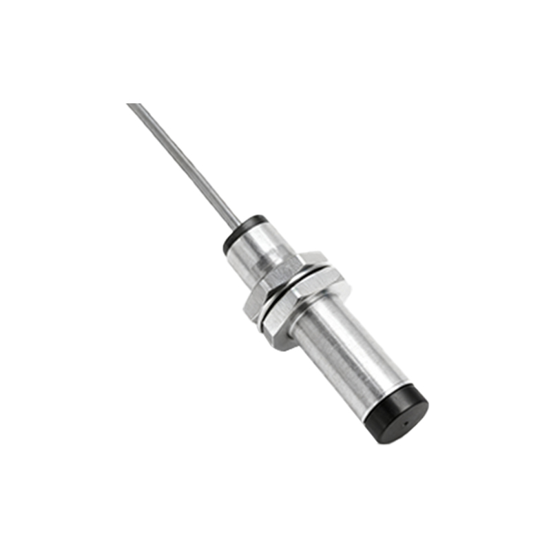
Proceed to open the housing. Many sensors have threaded or snap-fit designs. For threaded housings, use a wrench or pliers to unscrew the front or rear section. Apply steady pressure to avoid stripping threads. For snap-fit models, insert a flat tool into the seam and gently pry the housing apart. Take care not to damage sealing elements like O-rings or gaskets, which ensure ingress protection ratings such as IP67.
Once the housing is open, the internal components become visible. The core of an inductive proximity sensor includes an oscillator coil, ferrite core, signal processing circuit, and output switching element. The oscillator generates a high-frequency electromagnetic field at the sensor's face. When a metal object enters this field, eddy currents are induced, causing a change in oscillation amplitude. This change is detected by the circuit, triggering the output switch.
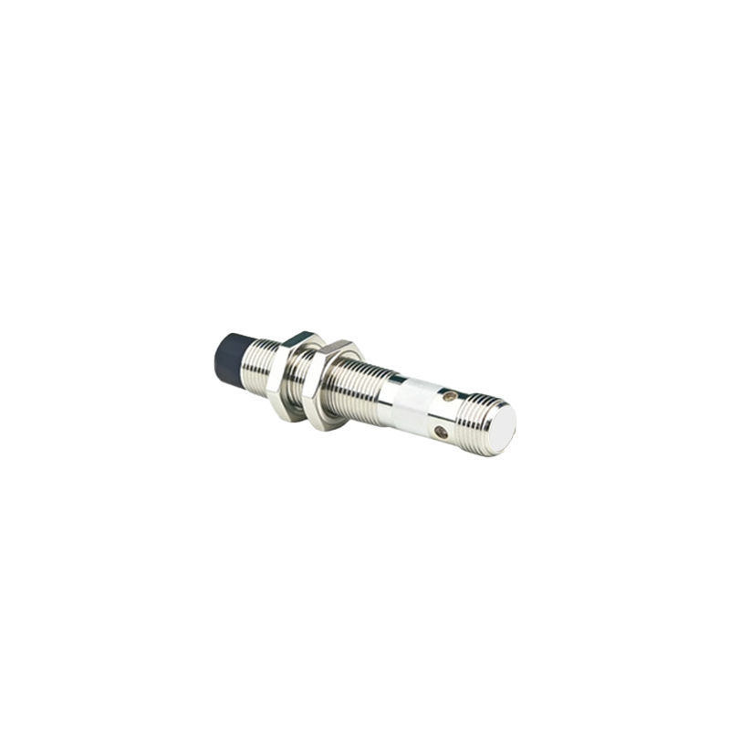
Observe the oscillator coil, usually wound around a ferrite core and positioned near the sensing face. The coil is often encapsulated in epoxy or resin for stability and protection. Inspect the coil for any signs of damage, such as broken wires or discoloration. Use a multimeter to measure the coil's resistance, comparing it to manufacturer specifications if available.
Examine the printed circuit board (PCB) that houses the signal processing electronics. The PCB typically includes components like transistors, resistors, capacitors, and an integrated circuit (IC) for signal amplification and processing. Look for indicators of wear, such as burnt traces, swollen capacitors, or corrosion. Clean the PCB with isopropyl alcohol and a soft brush if debris is present.
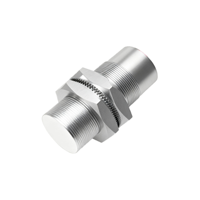
The output switching element, often a relay or solid-state switch, is mounted on the PCB. For DC sensors, this may be a transistor; for AC models, a triac or relay. Test the output with a multimeter in continuity mode to verify proper switching action. If the sensor has adjustable sensitivity or timing features, note the position of potentiometers or dip switches before making any adjustments.
After analysis, reassemble the sensor in reverse order. Ensure all components are correctly aligned and seated. Replace any damaged seals or gaskets to maintain environmental protection. Reconnect the wiring according to earlier notes, and perform a functional test by powering the sensor and introducing a metal object to the sensing face. Verify the output activates as expected.
Disassembling metal proximity sensors demystifies their operation and aids in troubleshooting. Common issues like false triggering or reduced sensing range can often be traced to coil damage, PCB faults, or worn seals. Regular maintenance, including cleaning and inspection, extends sensor lifespan and ensures reliable performance in demanding industrial environments.
In summary, metal proximity sensors are sophisticated devices combining electromagnetic principles with electronic processing. Through careful disassembly, one gains practical knowledge applicable to repair, customization, or optimization. Always refer to manufacturer guidelines for specific models, as designs may vary. With proper handling, these sensors continue to play a critical role in automation and safety systems worldwide.