Understanding Pull-Up Delay in Photoelectric Sensors
In the realm of industrial automation, photoelectric sensors are indispensable for object detection, positioning, and counting. A critical performance parameter often scrutinized by engineers is the sensor's response time, specifically the phenomenon known as "pull-up delay." This term refers to the time interval between the moment the sensor's light beam is no longer interrupted (the target object moves away) and the moment the sensor's output signal definitively switches from a low state (e.g., 0V, indicating detection) to a high state (e.g., 24V, indicating no detection). This delay is not instantaneous due to inherent electrical and processing characteristics within the sensor circuitry. Understanding and managing this delay is paramount for designing high-speed, reliable control systems where timing precision is crucial.
Primary Causes of Internal Pull-Up Delay
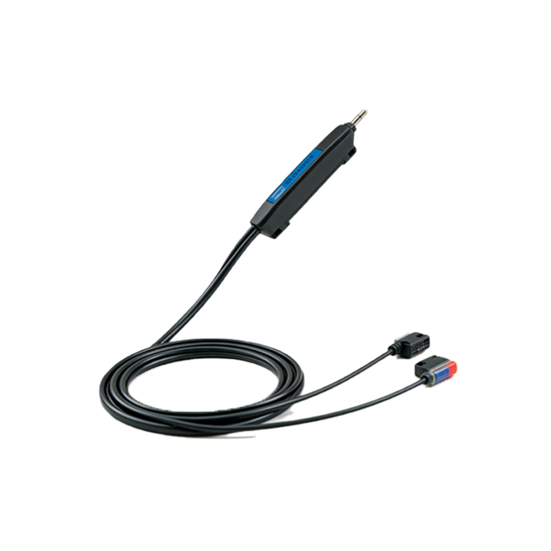
Several factors within the sensor's design contribute to pull-up delay. The photodetector component, typically a phototransistor or photodiode, has a finite recovery time after being saturated by the absence of light. When the beam is blocked, it conducts heavily; when unblocked, it requires a short period to stop conducting fully. Following the detector, the signal conditioning circuitry plays a significant role. Analog amplifiers and filters are used to clean the signal and improve signal-to-noise ratio, but these components introduce phase lag. Furthermore, the comparator circuit that decides the switching threshold has a propagation delay. Finally, in digital or smart sensors, the internal microcontroller or dedicated logic chip requires time to process the analog signal, apply hysteresis, and execute the logic to command the output stage. Each of these stages cumulatively builds the total pull-up delay.
The Impact on High-Speed Automation Systems
In low-speed applications, a pull-up delay of a few milliseconds may be negligible. However, in modern high-speed packaging, sorting, or assembly lines, even a delay of 1-2 milliseconds can lead to significant errors. For instance, an object traveling at 5 meters per second will move 10 millimeters during a 2ms delay. This can cause inaccurate positioning for a robotic pick-and-place unit, leading to product damage or misalignment. In high-speed counting applications, an excessive delay might cause the system to miss counting rapidly passing objects if the sensor output does not reset quickly enough for the next detection event. Therefore, characterizing and specifying the maximum pull-up delay is essential when selecting sensors for time-critical tasks.
Differentiating Pull-Up Delay from Other Timings
It is vital to distinguish pull-up delay from other related sensor timing parameters. "Response time" is often a generic term that may refer to either the turn-on delay (from no detection to detection) or the pull-up delay (from detection back to no detection), and they are not always symmetrical. "Switching frequency" is the maximum rate at which a sensor can reliably detect alternating presence and absence, and it is directly limited by the sum of the turn-on and pull-up delays. Additionally, "output hold time" or "on-delay/off-delay" are sometimes programmable functions added intentionally for debouncing, which are separate from the inherent physical pull-up delay. Data sheets should be consulted carefully for definitions.
Strategies for Minimizing and Compensating for Delay
Engineers can employ several strategies to mitigate the effects of pull-up delay. First, sensor selection is key. Choosing sensors specifically advertised for high-speed operation, with published pull-up delay values in the microsecond range, is the first step. Optical design also matters; a focused, modulated beam (like in ultrasonic or laser sensors) often allows for faster signal recovery than diffuse reflective modes. On the system side, programmable logic controllers (PLCs) can often compensate for known, consistent delays within their ladder logic or function block programming by using timers or by adjusting the trigger points for subsequent actions. For the most critical applications, using a sensor with a direct, unprocessed NPN open-collector output can sometimes offer the fastest response, though it may sacrifice noise immunity.
Measurement and Verification Techniques
Verifying the actual pull-up delay of a sensor in a specific application environment is good engineering practice. The most accurate method involves using an oscilloscope. One channel monitors the actual state of the light beam (using a synchronized reference signal or a second sensor), while the second channel monitors the sensor's output voltage. The time difference between the beam being restored and the output voltage crossing the logic-high threshold is the measured pull-up delay. Environmental factors such as ambient light, target reflectivity, and supply voltage stability can influence this measurement, so tests should be conducted under realistic operating conditions. This empirical data is more valuable than relying solely on datasheet typical values.
Conclusion: Balancing Speed, Stability, and Application Needs
In conclusion, pull-up delay is an inherent characteristic of photoelectric sensors stemming from their internal physics and electronics. While it cannot be eliminated entirely, its impact can be managed through informed sensor selection, proper optical mode choice, and system-level compensation. The goal is not always to seek the absolute minimum delay, but to find the optimal balance that ensures reliable detection without false triggers, meets the speed demands of the application, and maintains robustness in the industrial environment. A thorough understanding of this parameter empowers engineers to design more efficient, accurate, and dependable automation solutions.