Understanding Proximity Angle Sensor Fundamentals
Proximity angle sensors are critical components in modern industrial automation and motion control systems. These sensors detect the angular position or rotational speed of a target, typically a metallic object, without making physical contact. The core principle relies on electromagnetic induction or capacitive effects. As a metallic target approaches the sensor face at a specific angle, it alters the sensor's oscillation circuit. This change is converted into an electrical signal, providing precise angular data. Understanding this non-contact operation is the first step before examining the wiring, as it defines the sensor's output characteristics—whether it provides a simple on/off signal, an analog voltage proportional to the angle, or a digital pulse train. The sensor's housing, sensing face material, and environmental ratings (like IP67 for dust and water resistance) are also fundamental considerations that influence installation and wiring practices.
Deciphering the Sensor Datasheet and Pin Configuration
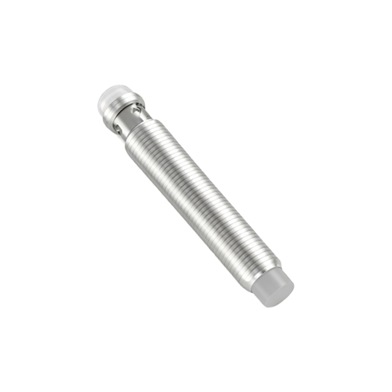
Before connecting a single wire, a thorough review of the manufacturer's datasheet is non-negotiable. This document holds the key to correct and safe operation. Primarily, identify the sensor type: 2-wire, 3-wire, or 4-wire. A 2-wire sensor acts as a switch in series with the power supply and load, simplifying wiring but requiring careful load matching. The 3-wire sensor is the most common, featuring separate lines for power supply positive (brown wire, typically +V), power supply negative/ground (blue wire, typically 0V), and the output signal (black wire). For analog or special digital outputs, a 4-wire configuration is standard, adding a separate wire for a second output or a diagnostic signal. The datasheet will explicitly state the pinout, voltage range (e.g., 10-30V DC), output type (PNP sourcing or NPN sinking), current rating, and switching frequency. Misinterpreting the PNP/NPN configuration is a common error that can damage the sensor or the controller.
Standard Wiring Diagram for a 3-Wire DC Sensor
The wiring for a standard 3-wire DC proximity angle sensor follows a logical pattern. First, establish the power circuit. Connect the positive lead from your DC power source (e.g., 24V) to the sensor's brown wire. Connect the negative lead from the power source to the sensor's blue wire and to the common ground of your system, such as the PLC's DC common terminal. This completes the sensor's internal electronics power loop. Next, handle the output circuit. For a PNP (sourcing) sensor, the black output wire provides a positive voltage when activated. This wire should be connected to the input terminal of your controller (PLC, counter, etc.). The controller input's common terminal must be connected to the power supply negative (0V). For an NPN (sinking) sensor, the black output wire sinks current to ground when active. Connect this wire to the controller input, but the controller input's common must be connected to the power supply positive. Always install an appropriate fuse in the power line for protection.
Integrating with Programmable Logic Controllers (PLCs)
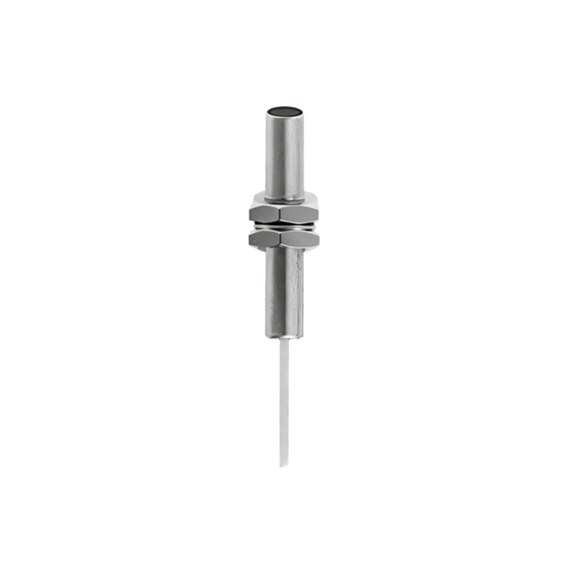
Integration with a PLC is a typical application. For a PNP sensor connected to a sinking-input PLC module, the wiring is straightforward: sensor brown to +24V, sensor blue to 0V and PLC COM, sensor black to the specific input point (e.g., I0.0). The PLC input is activated when the sensor detects a target, closing the circuit between +24V (via the sensor) and the input point, with current flowing into the PLC. For an NPN sensor connecting to a sourcing-input PLC module, the configuration reverses: sensor brown to +24V, sensor blue to 0V, sensor black to the PLC input point, and the PLC COM terminal is connected to +24V. Here, the activated sensor allows current to flow from the PLC input out to the sensor and to ground. Verifying the PLC module's input type (sinking or sourcing) is critical before making any connections to prevent malfunction.
Shielding, Grounding, and Noise Mitigation Techniques
In electrically noisy industrial environments, proper shielding and grounding are essential for reliable sensor operation. Many proximity angle sensors come with a shielded cable, where the braided shield surrounds the internal conductors. This shield must be grounded at only one end, typically at the control panel side, to the clean earth ground or the star ground point. Do not connect both ends of the shield, as this can create ground loops that induce noise. Keep sensor cables away from high-voltage power lines, motor drives, and welding equipment. If