Introduction to Proximity Switch Sensor Time Relays
In the realm of industrial automation and control systems, the integration of sensing and timing functions is paramount for achieving precise and efficient operations. A proximity switch sensor time relay represents a sophisticated combination of these two critical functionalities. Essentially, it is a device that utilizes a proximity sensor to detect the presence or absence of a target object without physical contact and incorporates a built-in time delay relay. This integration allows for control actions to be executed after a predetermined time interval following the detection event. The proximity sensor, often based on inductive, capacitive, or ultrasonic principles, provides the initial trigger. The time relay component then introduces a programmable delay, enabling sequenced operations, motor soft-start controls, or preventing rapid cycling in machinery. This synergy is fundamental in complex assembly lines, packaging systems, and safety interlocks where both accurate detection and controlled timing are non-negotiable.
Core Operating Principles and Technologies
The operation hinges on the seamless interaction between the sensor and timer modules. Inductive proximity sensors are most common in metal detection applications. They generate an electromagnetic field; when a metallic object enters this field, it causes a change in oscillation amplitude, which is detected by the sensor's circuit, producing a switching signal. Capacitive sensors work similarly but respond to both metallic and non-metallic materials by detecting changes in capacitance. Upon receiving the sensor's signal, the time delay relay is activated. Modern versions are predominantly solid-state, offering digital programmability for delay times. Timing modes are crucial: ON-delay (the relay activates after a set time once the sensor is triggered), OFF-delay (the relay remains active for a set time after the sensor signal ceases), and interval/one-shot modes. The timing accuracy, repeatability, and stability are key performance metrics, often specified with tolerances of ±0.5% or better, ensuring reliable process control.
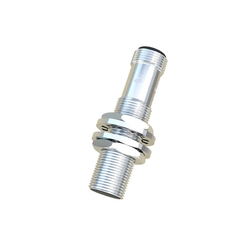
Key Selection Criteria for Industrial Applications
Selecting the appropriate proximity switch sensor time relay requires a meticulous evaluation of several parameters. First, the sensing technology must match the application: inductive for metals, capacitive for plastics, liquids, or granular materials, and ultrasonic for longer ranges or transparent objects. The sensing distance, or nominal range, must be chosen with a safety margin, typically 70-80% of the rated value to account for environmental factors and target variations. The timing range is equally critical; devices may offer delays from milliseconds to hours. The output type—whether relay contact (SPDT, DPDT), solid-state (transistor), or analog—must be compatible with the load (e.g., contactors, solenoids, PLC inputs). Environmental robustness is non-negotiable; look for high IP (Ingress Protection) ratings like IP67 for dust and water resistance, wide operating temperature ranges, and immunity to electrical noise (EMC compliance). Voltage supply compatibility (24V DC, 110-240V AC) must align with the plant's electrical infrastructure.
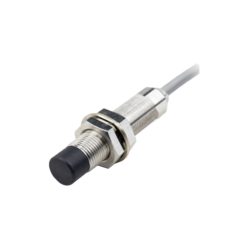
Installation, Wiring, and Configuration Best Practices
Proper installation is vital for optimal performance and longevity. Mount the sensor securely, ensuring the target approaches the correct sensing face. Maintain the specified lateral and axial distances from other metal objects or adjacent sensors to prevent mutual interference. For wiring, strictly adhere to the manufacturer's diagram. Shielded cables are recommended for long runs in electrically noisy environments, with the shield grounded at one end only. Connect the load correctly to the output terminals, respecting the rated current and voltage limits. Configuration involves setting the desired time delay and operating mode via potentiometers, dip-switches, or digital interfaces. For programmable models, use the provided software or front-panel buttons to input precise values. Always perform functional tests after installation: verify the sensor reliably detects the target and that the time delay initiates and concludes as programmed under actual operating conditions.
Common Applications and Use Case Scenarios
The versatility of these integrated devices finds application across numerous industries. In automotive manufacturing, they control robot welding sequences—the sensor detects a car body panel, and a timed delay ensures the welding gun fires at the exact correct moment. In packaging machinery, a capacitive sensor detects a filled bottle, triggering a timer that delays the capping mechanism until the bottle is perfectly positioned. They are indispensable for conveyor belt systems, where an object's detection can start a delay after which a diverter gate activates to route the item. For motor control, they facilitate soft-start sequences or automatic star-delta switching. In safety systems, an OFF-delay function can keep a machine guard locked for a set period after a stop signal, ensuring all motion has ceased before access is permitted. These examples underscore their role in enhancing efficiency, precision, and safety.