Introduction to High-Speed Gear Proximity Sensing
In modern industrial automation, monitoring rotational speed and position is critical for process control, safety, and predictive maintenance. High-speed gear proximity sensors are specifically engineered for this demanding task. These non-contact sensors, typically inductive or capacitive, detect the teeth of a rotating gear without physical interaction. The core principle involves generating an electromagnetic field; as a gear tooth passes through this field, it causes a detectable change in oscillation amplitude or frequency. This change is converted into a clean, digital pulse signal. The primary advantage lies in their durability and reliability in harsh environments—resistant to oil, dust, and vibration—making them ideal for applications in automotive manufacturing, packaging machinery, and turbine monitoring where precise, high-frequency counting is paramount.
Sensor Selection and Key Technical Parameters
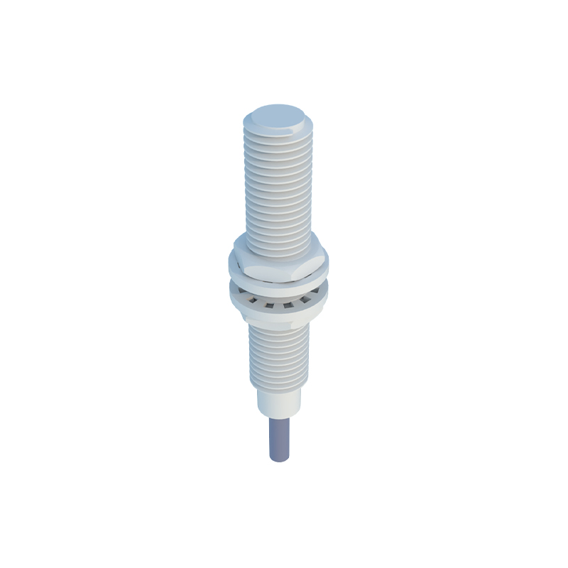
Choosing the correct sensor is foundational to successful integration. Key specifications must be carefully evaluated. First, the switching frequency, measured in Hertz (Hz), must exceed the maximum possible tooth-passing frequency of the gear. For a gear with N teeth rotating at R RPM, the frequency is calculated as (N R) / 60. A sensor with a 10 kHz switching frequency can reliably detect a 100-tooth gear spinning at 6000 RPM. Second, the sensing distance and the mounting gap are crucial; the sensor must be positioned close enough for reliable detection but outside the mechanical tolerance zone to prevent collision. Third, output type is critical: PNP (sourcing) or NPN (sinking) transistor outputs must match the PLC input card's specifications. Additionally, factors like housing material (stainless steel for corrosive environments), temperature rating, and output protection (short-circuit and reverse polarity) ensure long-term system integrity.
Wiring and Interfacing with PLC Digital Input Modules
Proper electrical interfacing is the bridge between the sensor and the control system. A standard three-wire DC sensor requires a power supply (typically 10-30V DC), a ground connection, and a signal output wire. The sensor's output wire connects directly to a discrete input channel on the PLC module. For a PNP sensor, the output provides positive voltage to the PLC input; thus, the PLC input common is connected to the DC negative. For an NPN sensor, the output sinks current to ground, requiring the PLC input common to be connected to DC positive. Shielding the cable is essential to prevent electromagnetic interference (EMI) from corrupting the high-speed pulse signal, especially in panels with motor drives and contactors. The shield should be grounded at the PLC end only to avoid ground loops. Always consult both the sensor and PLC hardware manuals for specific terminal designations and wiring diagrams.
PLC Programming Strategies for Speed and Diagnostics
Within the PLC programming environment, the high-speed pulse train is processed to extract valuable data. Most modern PLCs offer dedicated high-speed counter (HSC) function blocks or input filters configurable for fast inputs. The programmer must configure the hardware counter in the PLC's system settings to match the input channel used. The primary logic involves using the counter's accumulated value. By resetting the counter at precise time intervals (e.g., every second) using a timer, the count value directly represents the frequency in Hz. This frequency can be scaled to RPM or used for comparison against setpoints for overspeed or underspeed alarms. Advanced diagnostic routines can be implemented by monitoring the counter's status. A stalled machine will result in a zero frequency, while a broken sensor wire or failed sensor often results in a permanently active or inactive input signal, which can be flagged by monitoring for an abnormally constant state over a defined period.
System Calibration, Testing, and Troubleshooting
Post-installation calibration and systematic testing validate the entire measurement chain. Begin by verifying the sensor output with a multimeter or oscilloscope while manually rotating the gear; a clean, consistent voltage swing should be observed. Next, monitor the raw PLC input status bit to confirm it toggles with each tooth. Then, verify the counted value in the HSC register matches the physical rotation over a timed interval. Common issues include erratic counts due to insufficient mounting stability, electrical noise, or an incorrect air gap. If counts are missed, check if the switching frequency is adequate or if the sensor is misaligned. If the input is permanently active, check for a wiring short or sensor failure. A robust system includes HMI indicators for real-time RPM, counter status, and diagnostic flags, enabling operators to identify faults quickly and minimize machine downtime.
Conclusion and Best Practices
Integrating