In industrial automation and electronic design, proximity switch sensors play a crucial role in detecting the presence or absence of objects without physical contact. While technical specifications are vital, visual references—proximity switch sensor photos—provide immediate, practical understanding for engineers, technicians, and procurement specialists. This visual guide explores the common types, key features visible in photographs, and typical application scenarios captured through imagery.
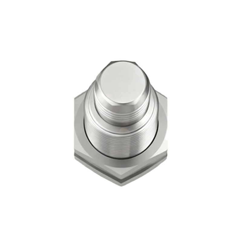
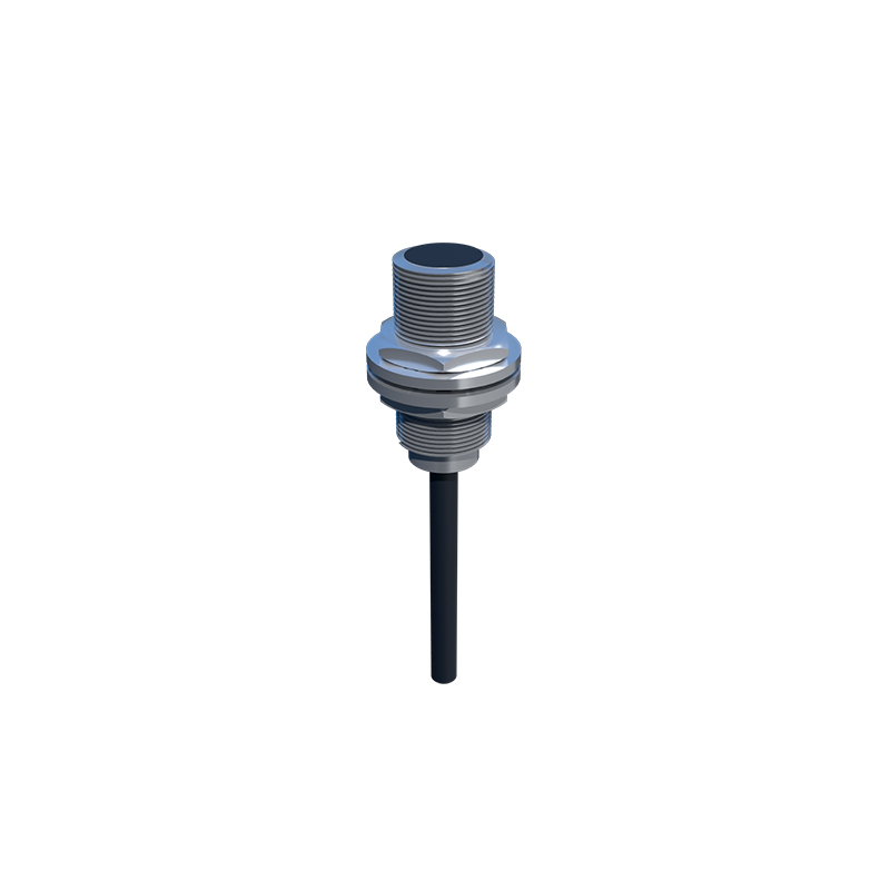
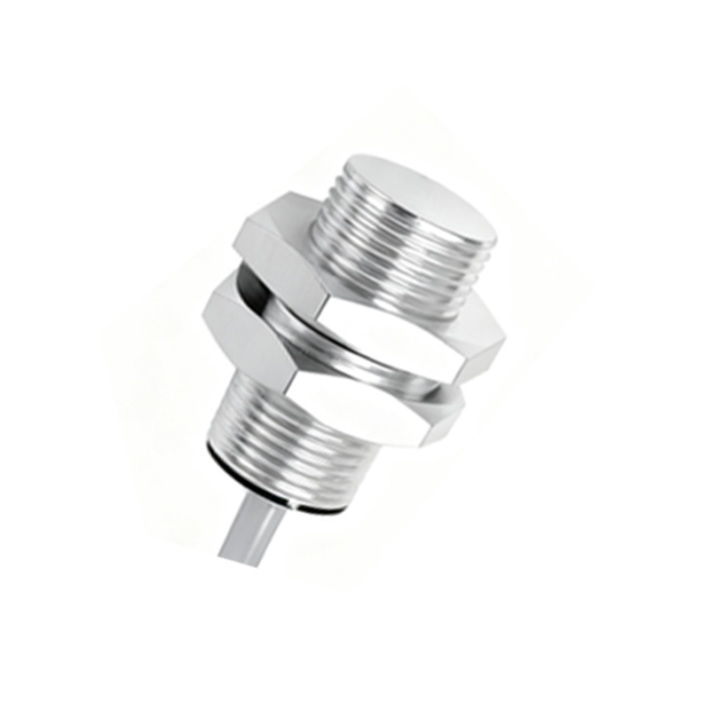
A glance at a gallery of proximity switch sensor photos reveals a world of variety. The most immediate visual distinction is the housing shape and material. Cylindrical metal housings, often in stainless steel or nickel-plated brass, dominate images of inductive proximity sensors. These photos frequently show a sensing face at one end, with a threaded barrel for easy mounting in machinery. The robust, metallic appearance visually communicates their use in harsh industrial environments like metalworking or automotive assembly lines. In contrast, photos of capacitive proximity sensors might show similar cylindrical forms but sometimes with plastic or polymer sensing faces, hinting at their ability to detect non-metallic materials like liquids, wood, or plastics.
Photographs effectively highlight the critical form factor differences. Tubular sensors, ranging from miniature 4mm diameters to larger 30mm versions, are commonly depicted alongside a coin or ruler for scale, providing instant size context. Rectangular or block-style sensors appear in photos with distinct mounting brackets, often shown installed on conveyor system frames or robotic arm fixtures. Images of slot-type or fork sensors clearly display a U-shaped profile with an emitter on one leg and a receiver on the other, perfectly visualized for object counting or edge detection tasks. Ring-shaped sensors, photographed encircling a wire or small part, immediately convey their use for verification of threaded components or continuous material monitoring.
Wiring and connection interfaces are another aspect where photos offer superior clarity to text alone. Close-up shots often reveal the cable exit style: pre-wired cables with PUR or PVC sheathing, shown with strain relief glands; or quick-disconnect models where the sensor body and cable connector are pictured separately. Images clearly show connector types, such as the common M8 or M12 3-pin, 4-pin, or 5-pin coded connectors, with the pin arrangement visible. Some photos include color-coded wiring diagrams on the sensor label, a detail immensely helpful for installation. LED status indicators are a standout visual feature; operational photos in dim settings often show a bright red or green LED illuminated, providing instant diagnostic information about power and output state.
The true value of proximity sensor photos emerges in application context shots. Instead of an isolated product-on-white background, contextual images tell a story. A photo might show a cylindrical inductive sensor mounted precisely opposite a metal flag on a rotating shaft, visually explaining its role as a speed or position sensor. Another could capture a small rectangular diffuse photoelectric sensor detecting a cardboard box on a conveyor, with the focused beam path implied. Images of wash-down sensors in food packaging lines show their smooth, polished housings and sealed connectors, visually attesting to their IP67 or IP69K ratings. Pictures of long-range sensors might show them detecting a pallet several feet away in a warehouse automation setting.
When analyzing photos for selection, several visual cues are paramount. The sensing distance, often engraved on the housing (e.g., "Sn: 5mm"), is a key spec captured in macro photography. The output configuration is typically indicated by symbols on the label: a PNP or NPN schematic diagram, or an AC/DC designation. Photos of the nameplate reveal the part number, voltage range, and compliance markings (CE, UL). For designers, images showing the sensor's footprint and mounting hole patterns are essential for integration into mechanical drawings.
Lighting and environment in the photo also convey unspoken specifications. A sensor pictured in a clean, bright laboratory setting suggests high-precision applications. The same sensor type shown covered in light metal chips or with water droplets on its face communicates durability and ingress protection. Comparison photos are particularly effective. Side-by-side images of a standard sensor and a factor-1 (flush-mountable) sensor clearly show the recessed sensing face of the latter, which prevents detection of the surrounding metal mount.
For troubleshooting, comparative photos are invaluable. An image of a correctly installed sensor with proper clearance from metal surfaces contrasts with one mounted flush in a metal bracket without the specified non-ferrous surround, visually explaining false triggering issues. Photos showing damaged sensing faces, bent housings, or cracked cables help diagnose common failure modes.
In summary, proximity switch sensor photos serve as an indispensable tool bridging data sheets and real-world implementation. They accelerate identification, clarify mounting and wiring, illustrate operational principles, and demonstrate suitable environments. A well-curated collection of images, from macro product details to broad application scenes, forms a visual database that enhances understanding, ensures correct selection, and aids in efficient maintenance