Introduction to Two-Wire Proximity Sensors
In the realm of industrial automation and control systems, proximity sensors are indispensable components for detecting the presence or absence of an object without physical contact. Among the various configurations, the two-wire proximity sensor stands out for its simplicity and cost-effectiveness. Unlike its three-wire or four-wire counterparts, a two-wire sensor integrates seamlessly into a DC circuit by connecting in series with the load. This design eliminates the need for a separate power supply wire, as the same two wires are used to carry both the operating power for the sensor and the switching signal to the controller or load. This fundamental characteristic makes it a preferred choice in applications where wiring complexity, space constraints, and installation costs are critical considerations. Its operation is based on the principle of modulating the current flow in the line to indicate the sensor's state, a concept that will be explored in detail.
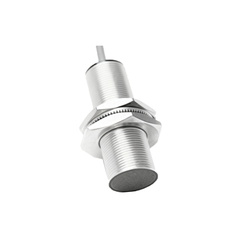
Operating Principle and Circuit Design
The core functionality of a two-wire DC proximity sensor revolves around its ability to control current flow. In its normal, non-detecting state (often termed the "off" state), the sensor presents a high impedance to the circuit, allowing only a small leakage current, typically a few milliamperes, to pass through. This "off-state current" is sufficient to power the sensor's internal oscillator and amplifier circuits but is below the threshold required to activate the connected load, such as a PLC input module or a relay coil. When a target enters the sensor's detection field, the internal electronic switch closes, significantly lowering the sensor's impedance. This allows a much higher "on-state current" to flow, which is adequate to both power the sensor and reliably switch the load. The entire system operates within a specified voltage range, and the load must be carefully selected to ensure the voltage drop across the sensor in the "on" state does not compromise the load's operation. This inherent voltage drop is a key design parameter.
Key Advantages in Industrial Applications
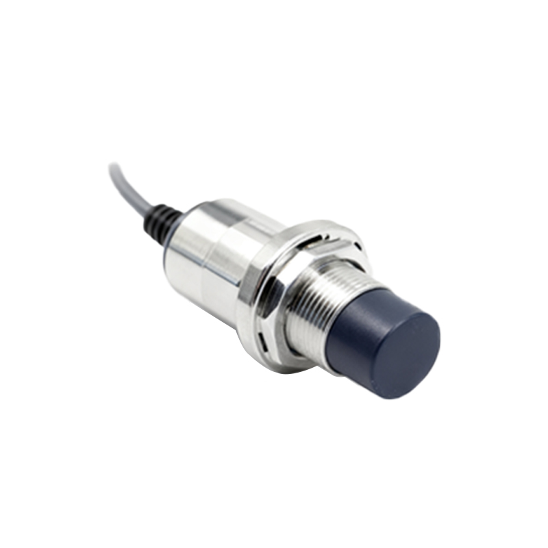
The two-wire design offers several compelling advantages that solidify its position in the market. Primarily, it reduces installation time and material costs by halving the number of wires needed compared to a three-wire sensor. This simplification extends to control panel design, requiring fewer terminals and less space. Furthermore, the wiring polarity is generally not critical for AC two-wire sensors, though DC versions often require correct polarity. This can further speed up installation and reduce wiring errors. From a maintenance perspective, the simpler wiring topology makes troubleshooting more straightforward. These sensors are also known for their robustness and ability to handle relatively high inrush currents from inductive loads like contactor coils. Their streamlined design often translates to a more compact housing, enabling installation in tight spaces where a three-wire sensor with its separate power cable might not fit.
Critical Considerations and Limitations
Despite their advantages, two-wire proximity sensors come with specific limitations that engineers must account for during system design. The most significant is the inherent voltage drop, or "burden voltage," across the sensor when it is in the conducting ("on") state. This voltage drop, which can range from 2 to 8 volts depending on the model and current, reduces the voltage available to the load. If not properly calculated, it can lead to a PLC input failing to register a "ON" signal or a relay failing to energize. Consequently, the minimum operating voltage of the load must be greater than the supply voltage minus the sensor's maximum "on-state" voltage drop. Additionally, the sensor's leakage current in the "off" state must be lower than the minimum holding current of the load to prevent false activation. These constraints necessitate careful compatibility checks between the sensor, power supply, and the connected load to ensure reliable system performance.
Selection Criteria and Installation Best Practices
Selecting the appropriate two-wire proximity sensor requires a systematic evaluation of application parameters. First, determine the required sensing distance, target material (ferrous, non-ferrous, or all metals), and the sensor's housing material (e.g., nickel-plated brass, stainless steel) for environmental durability. The operating voltage range (e.g., 10-30 VDC) must match the available power supply. Crucially, verify the electrical characteristics: ensure the sensor's maximum "off-state" leakage current is below the load's minimum non-activation current, and confirm that the supply voltage minus the sensor's "on-state" voltage drop provides sufficient voltage for the load. During installation, always refer to the manufacturer's datasheet for wiring diagrams. Use shielded cables in electrically noisy