Introduction to Photoelectric Sensors
Photoelectric sensors are widely used in industrial automation for detecting the presence, absence, or position of objects without physical contact. They operate by emitting a light beam (usually infrared, visible, or laser) and measuring changes in the received light due to interruption or reflection. These sensors are essential in applications such as conveyor systems, packaging machinery, and safety barriers, offering high precision, fast response times, and reliability in harsh environments. Understanding their wiring methods and schematic diagrams is crucial for proper installation, troubleshooting, and integration into control systems. This article delves into the core principles, common wiring configurations, and practical examples to help engineers and technicians implement photoelectric sensors effectively.
Basic Operating Principles
Photoelectric sensors function based on light modulation techniques. They consist of three main components: an emitter (light source), a receiver (photodetector), and signal processing circuitry. The emitter generates a modulated light beam to reduce interference from ambient light. When an object interrupts or reflects this beam, the receiver detects the change in light intensity, converting it into an electrical signal. This signal is then processed to trigger an output, such as a switch or digital signal. Common types include through-beam (opposed), retro-reflective, and diffuse (proximity) sensors, each with distinct working principles. Through-beam sensors have separate emitter and receiver units, offering long detection ranges and high accuracy. Retro-reflective sensors use a reflector to bounce light back to the receiver, simplifying alignment. Diffuse sensors rely on light reflecting directly from the target, making them suitable for close-range applications.
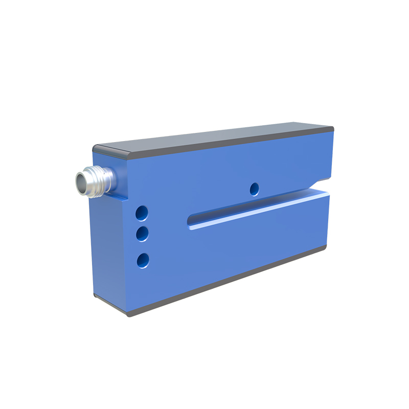
Wiring Methods for Photoelectric Sensors
Proper wiring is vital for sensor performance and safety. Photoelectric sensors typically have three or four wires, including power supply, output, and ground connections. The wiring method depends on the sensor type (e.g., NPN or PNP output) and the control system (e.g., PLC or relay). For DC sensors, common configurations are: 1) NPN (sinking) output, where the output switches the negative side of the load to ground, often used in Asian and European systems. 2) PNP (sourcing) output, where the output switches the positive side of the load to the power supply, prevalent in North America. Wiring diagrams usually indicate color codes: brown for positive voltage (V+), blue for ground (0V), black for output signal, and white for auxiliary functions. Always refer to the manufacturer's datasheet for specific details. Ensure correct voltage ratings (e.g., 10-30 VDC) and polarity to prevent damage. Shielded cables may be necessary in noisy environments to reduce electromagnetic interference.
Schematic Diagrams and Examples
Schematic diagrams provide a visual guide for connecting photoelectric sensors in circuits. A typical diagram includes symbols for the sensor, power supply, load (e.g., PLC input, relay, or indicator), and protective devices like fuses. For example, in a through-beam sensor setup with PNP output: Connect the brown wire to the positive terminal of a 24VDC power supply, the blue wire to the negative terminal, and the black output wire to the PLC input module. The load is placed between the output and ground. Diagrams also show how to wire multiple sensors in parallel or series, considering current draw and voltage drop. Retro-reflective sensors might include a wire for teaching or sensitivity adjustment. Always include a disconnect switch and proper grounding in schematics for safety. Use CAD software or standardized symbols (per IEC or ANSI standards) to create clear diagrams, ensuring consistency across documentation.
Installation and Troubleshooting Tips
Installation requires attention to alignment, environmental factors, and mechanical stability. Mount sensors securely to avoid vibration-induced errors. Align through-beam and retro-reflective types precisely using alignment tools or indicators. For diffuse sensors, maintain the recommended sensing distance and angle. Avoid placing sensors near strong light sources, dust, or steam, which can cause false triggers. In wiring, check for loose connections, corrosion, or short circuits. Use multimeters to verify voltage and continuity. Common issues include no output signal, intermittent operation, or false detections. Troubleshoot by inspecting the light path for obstructions, cleaning lenses, and testing with a known good object. Adjust sensitivity settings if available. Refer to error codes in smart sensors with diagnostic features. Regular maintenance, such as cleaning and calibration, extends sensor life and ensures reliable performance.
Advanced Applications and Integration
Modern photoelectric sensors offer advanced features like background suppression, fiber-optic options, and IO-Link communication for Industry 4.0. Background suppression sensors ignore objects beyond a set distance, useful in complex environments. Fiber-optic sensors allow detection in tight spaces or extreme temperatures by separating the sensing head from the electronics. Wiring for these variants follows similar principles but may include additional wires for configuration or data transmission. When integrating into networked systems, ensure compatibility with protocols like Ethernet/IP or Profinet. Schematics should depict communication lines and power distribution clearly. Always perform functional tests after installation, simulating real-world conditions. As automation evolves, understanding these wiring and schematic fundamentals enables seamless adoption of smart sensor technologies, enhancing efficiency and safety in industrial settings.