Understanding Photoelectric Sensor Fundamentals
Photoelectric sensors are pivotal components in modern industrial automation, converting light signals into electrical outputs. Zhongming, a prominent manufacturer in the field, produces sensors renowned for their reliability in detecting objects, measuring distances, and ensuring precision in control systems. These sensors typically operate by emitting a light beam—often infrared or visible—and measuring the reflection or interruption to generate a digital signal. The digital output, usually in the form of a high/low voltage (e.g., 5V for logic high, 0V for logic low), interfaces seamlessly with microcontrollers, PLCs, or data acquisition systems. For engineers, grasping this basic principle is essential before delving into signal reading techniques, as it underpins the sensor's response to environmental factors like ambient light, object reflectivity, and alignment.
Hardware Setup and Connection Protocols
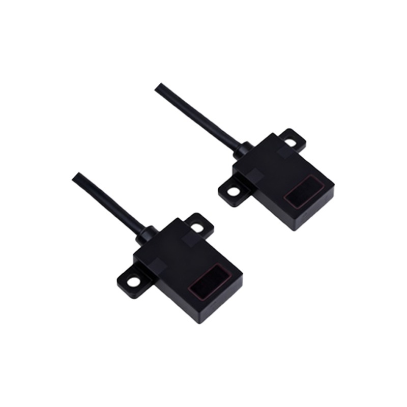
To read digital signals from Zhongming photoelectric sensors, start with a proper hardware configuration. Most Zhongming models feature three wires: power (Vcc, typically 12-24V DC), ground (GND), and output (OUT). Connect the Vcc and GND to a stable power supply within the specified range to avoid signal noise or damage. The OUT pin should be linked to the input channel of your reading device, such as a microcontroller's digital input pin or a PLC's input module. Ensure shielded cables are used in electrically noisy environments to prevent interference. Additionally, some sensors offer adjustable sensitivity via potentiometers; calibrate these settings based on the application—for instance, reducing sensitivity in bright conditions to avoid false triggers. Always refer to the sensor's datasheet for pinouts and voltage tolerances, as mismatches can lead to erroneous readings or hardware failure.
Signal Interpretation and Digital Logic
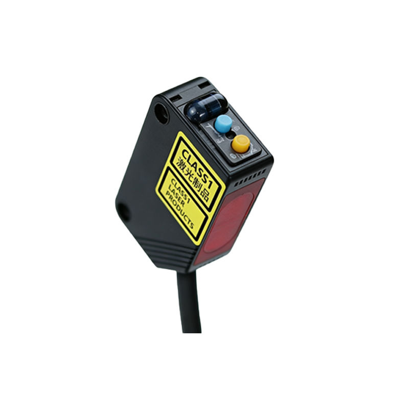
Zhongming photoelectric sensors output digital signals that adhere to standard logic levels, making them compatible with most industrial systems. When the sensor detects an object or a specific condition (e.g., a beam break), the OUT pin switches to a high state (logic 1); otherwise, it remains low (logic 0). Engineers must account for the sensor's response time—often in milliseconds—to ensure accurate timing in high-speed applications. Use an oscilloscope or logic analyzer to verify signal integrity, checking for clean transitions without excessive ringing or noise. In programmable setups, code logic should include debouncing routines if the sensor is prone to mechanical vibrations. For example, in a microcontroller-based system, a simple Arduino script can read the signal:int sensorValue = digitalRead(pin); followed by conditional statements to trigger actions. Understanding this digital logic is crucial for integrating sensors into larger automation networks.
Software Integration and Data Processing
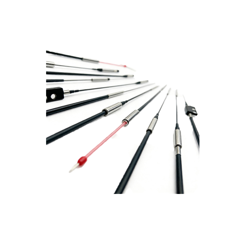
Integrating Zhongming sensor data into software systems enhances functionality in automation projects. For PLCs, ladder logic or structured text can be employed to monitor the digital input and execute control sequences, such as activating a conveyor belt when an object is detected. In PC-based applications, use communication protocols like Modbus or Ethernet/IP if the sensor is networked, or directly read via GPIO on single-board computers. Develop algorithms to process signal patterns—for instance, counting objects by tracking rising edges of the digital waveform. Implement error-handling routines to manage signal drops or anomalies, logging data for predictive maintenance. Software tools like MATLAB or Python libraries (e.g., RPi.GPIO for Raspberry Pi) facilitate advanced analysis, enabling engineers to optimize sensor placement and calibration based on real-time feedback.
Troubleshooting Common Reading Issues
Engineers often encounter challenges when reading digital signals from photoelectric sensors. If the sensor outputs inconsistent signals, first check power stability and grounding, as voltage fluctuations can cause erratic behavior. Inspect the optical lens for dirt or obstructions, and ensure the target object is within the sensor's range and reflectivity specifications. For false triggers, adjust sensitivity settings or install light shields to block ambient interference. Use a multimeter to measure output voltage; if it deviates from expected logic levels (e.g., 2.5V instead of 5V), the sensor may be faulty or overloaded. In networked systems, verify communication cables and protocol configurations. Documenting these steps in a maintenance log can streamline future diagnostics, ensuring long-term reliability in industrial environments.
Applications and Best Practices
Zhongming photoelectric sensors are widely used in packaging, assembly lines, and safety systems, where accurate digital signal reading is paramount. Best practices include regular calibration based on environmental changes, such as temperature shifts that affect light emission. Employ redundancy by using multiple sensors in critical applications to cross-verify signals. Keep firmware and software updated to leverage improved features from Zhongming. When designing systems, consider fail-safe mechanisms—like defaulting to a low signal state during power loss—to prevent accidents. By adhering to these guidelines, engineers can maximize sensor performance, reduce downtime, and enhance overall system efficiency in diverse industrial settings.