Understanding the Flashing Phenomenon
A flashing or blinking indicator on a photoelectric sensor is a common occurrence in industrial automation and control systems. This visual cue is not inherently a sign of failure; rather, it is a deliberate communication feature designed by manufacturers. The flashing pattern serves as a diagnostic tool, conveying the operational status of the sensor to technicians and engineers. Typically, the light-emitting diode (LED) on the sensor body is programmed to flash in specific sequences or colors. Each sequence corresponds to a particular state, such as power-on self-test, object detection, signal output activity, or an error condition. Understanding this basic premise is the first step in effective troubleshooting, transforming a seemingly erratic blink into a readable code.
Common Operational Reasons for Flashing
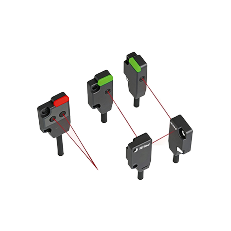
In many cases, flashing is a sign of normal operation. Upon initial power application, most sensors undergo a brief self-check, indicated by a rapid flash. Following this, a steady flash at a regular interval often signifies that the sensor is powered, functional, and in its "standby" or "no target" state. When the sensor detects an object within its sensing range, the flash pattern typically changes. This change might involve the LED switching from flashing to a solid ON state, or it might flash at a different frequency. This immediate visual feedback is invaluable for aligning the sensor during installation or verifying its detection capability during routine checks without needing a multimeter or PLC interface.
Flashing as an Indicator of Problems
When the flashing pattern deviates from the documented normal behavior described in the sensor's datasheet, it indicates a potential issue. A fast, erratic, or alternating color flash (on models with multi-color LEDs) usually points to a fault condition. Common problems signaled this way include wiring errors, such as reversed polarity or incorrect voltage supply. Inconsistent or weak flashes can suggest power supply instability or voltage drops in the circuit. For modulated sensors, a specific flash code might indicate electrical noise interference disrupting the signal. Environmental factors are also a major culprit; accumulation of dust, dirt, or condensation on the lens can cause the received light signal to fluctuate, leading the sensor to flash erratically as it struggles to maintain a stable detection state.
Troubleshooting Step-by-Step Guide
Begin the troubleshooting process by consulting the specific sensor's manual to decode the exact meaning of its flash pattern. Next, verify the power supply with a voltmeter to ensure it matches the sensor's specifications and is stable. Inspect all wiring connections for tightness, corrosion, or damage, paying close attention to correct polarity and grounding. Physically clean the sensor's lens and the reflector (if used) with appropriate materials. For diffuse sensors, check the target object's color, texture, and angle, as highly reflective or absorbent surfaces can cause unreliable detection. Temporarily shield the sensor from strong ambient light sources, such as sunlight or welding arcs, which can saturate the receiver. Finally, if possible, test the sensor in a controlled environment or swap it with a known-good unit to isolate the fault to the sensor itself or the external setup.
Advanced Considerations and Electrical Noise
In electrically noisy environments, such as those near variable frequency drives, motors, or welding equipment, photoelectric sensors can flash due to electromagnetic interference (EMI). This noise can be induced on the signal or power lines, causing the sensor's internal circuitry to misinterpret signals. To mitigate this, ensure sensor cables are routed away from power cables, using shielded cables grounded at only one end. Installing ferrite cores on the sensor cables near the connections can suppress high-frequency noise. Additionally, check if the sensor housing is properly grounded. For AC-powered sensors, ensure the neutral line is correctly connected. Using sensors with robust noise immunity ratings and DC models with surge protection devices can significantly enhance reliability in harsh electrical environments.
Preventive Maintenance and Best Practices
Preventing unnecessary flashing and sensor faults involves a regimen of proactive maintenance. Establish a regular schedule for cleaning optical components. Implement environmental protections like installing physical guards or air blowers to keep lenses clear in dusty areas. Use drip covers or housings for wet environments. During system design, select the correct sensor type (through-beam, retro-reflective, diffuse) for the application to avoid marginal detection scenarios. Ensure the power supply is adequately sized and consider using a dedicated, regulated supply for sensitive sensor networks. Proper installation, following the manufacturer's guidelines for sensing distance, alignment, and mounting stability, is the most effective way to ensure a steady, reliable indicator light and, by extension, a reliable automation process.