Common Assembly-Related Faults in Proximity Sensors
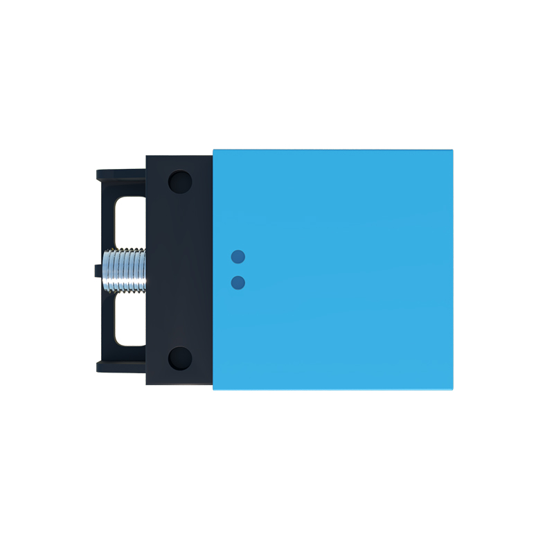
Proximity sensors, while robust in design, are highly susceptible to performance degradation and outright failure due to improper assembly practices. A primary category of faults stems from mechanical mounting errors. Incorrect sensor orientation relative to the target is a frequent issue; for inductive sensors, the sensing face must be parallel to the target surface for optimal operation. Angular misalignment can drastically reduce the effective sensing distance. Overtightening of the mounting nuts is another critical error. Excessive torque can distort the sensor housing, potentially damaging internal coils or electronic components, and may also alter the precise air gap between the sensing face and the target. Conversely, under-tightening leads to vibration-induced movement, causing inconsistent sensing signals and eventual mechanical wear on the housing and cables.
Electrical Connection and Wiring Pitfalls
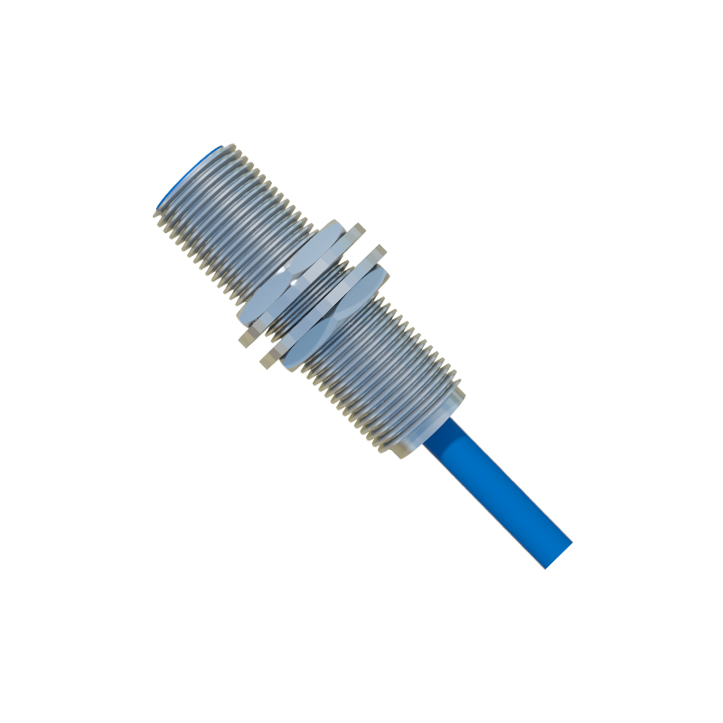
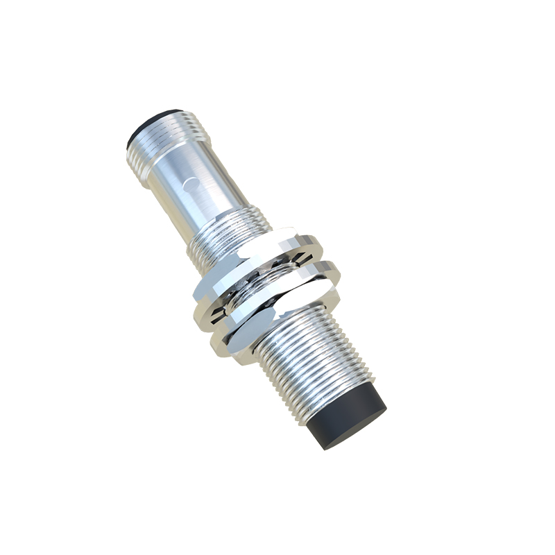
The electrical interface is a major failure point if assembly guidelines are neglected. Improper wire stripping and termination top the list. Stranded wires that are not properly fitted into ferrules can lead to stray strands causing short circuits. Over-tightening terminal screws can cut through conductors, creating intermittent connections that are notoriously difficult to diagnose. For sensors with quick-disconnect (M12, M8) connectors, failure to achieve a positive lock and a complete seal can allow ingress of contaminants and moisture. Furthermore, neglecting to provide adequate strain relief for the cable at the entry point to the junction box or sensor itself places stress on the internal solder joints, leading to wire breakage over time. Mixing up wiring configurations (e.g., connecting an NPN sensor to a PNP input module, or incorrect common wire connection) will immediately render the sensor inoperative or cause damage.
Environmental Sealing and Contamination Failures
Many proximity sensor failures are not immediate but develop due to the gradual breakdown of environmental protection. A critical assembly step often overlooked is ensuring the integrity of IP-rated seals. For sensors rated IP67 or higher, this includes correctly installing and torquing sealing glands on cable entries, verifying that O-rings on housing threads are present and undamaged, and ensuring that blanking plugs are securely fastened on unused ports. Contamination during assembly is a silent killer; introducing metal shavings, cutting fluid, or dust into the sensor's sensing field or electrical connections during installation can cause erratic behavior. Inductive sensors, in particular, can be affected by metallic debris adhering to the sensing face, which alters their magnetic field and detection characteristics.
Diagnostic Procedures for Assembly Faults
Systematic diagnosis is key to isolating assembly-related faults. Begin with a visual and mechanical inspection: check for physical damage, verify mounting alignment and tightness, and inspect cable strain relief. Use a non-conductive tool to gently check for any looseness in the sensor body. Electrically, a multimeter is essential. For a 3-wire DC sensor, measure the voltage between the output wire and common while actuating the target. An inconsistent or absent voltage swing indicates a problem. Monitoring the output with an oscilloscope can reveal noise or intermittent dropouts caused by poor connections. For checking sensing performance, use the manufacturer-specified target material and measure the actual switching distance with feeler gauges, comparing it to the datasheet specification. A significant reduction often points to internal damage from shock or contamination.
Preventive Measures and Best Practices for Assembly
Preventing assembly faults requires adherence to a disciplined protocol. First, always consult the sensor's datasheet and installation manual for specific torque values, sensing distances, and environmental limitations. Use calibrated torque tools for mounting nuts and cable glands to avoid over- or under-tightening. Employ proper cable preparation tools, including wire strippers and crimping tools for ferrules, to ensure clean, secure terminations. Implement a pre-power checklist: verify wiring against the diagram, check connector locks, and clean the sensing face. For critical applications, perform a functional test with the actual target before final system integration. Establishing and following standardized work instructions for sensor installation is the most effective long-term strategy to eliminate variability and prevent the costly downtime associated with assembly-related failures.