Understanding the Core Limitation
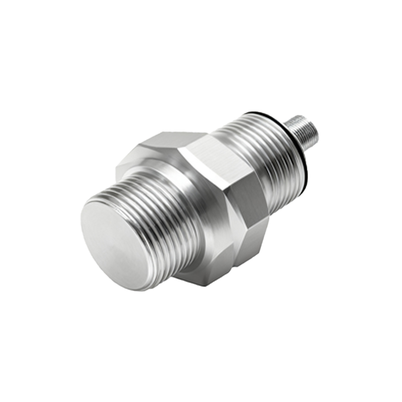
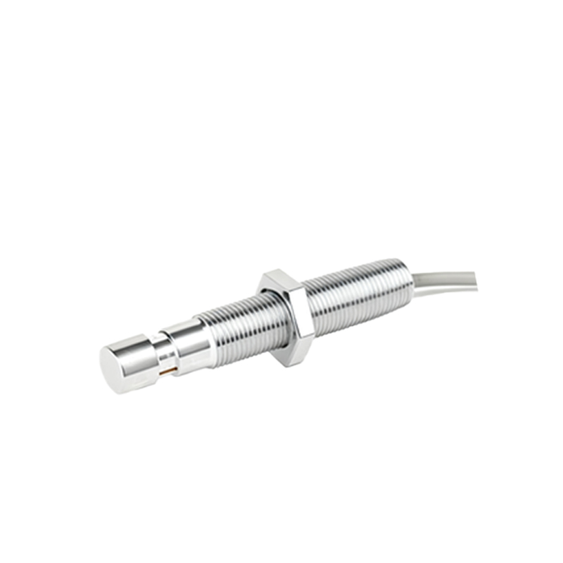
In industrial automation and machinery design, proximity sensors are indispensable components for non-contact detection of metallic or non-metallic objects. A frequent and critical challenge encountered during installation and system integration is the insufficient length of the sensor's pre-attached cable. Factory-supplied cables are typically standardized to a common length, often ranging from 2 to 5 meters. This standardization, while cost-effective for manufacturers, frequently clashes with the complex and varied spatial realities of modern machinery layouts, control cabinet placements, and production line configurations. When the sensor's fixed cable falls short, it can halt installation, necessitate costly design changes, or lead to unsafe temporary wiring practices that compromise system reliability and safety.
Primary Risks of Inadequate Cable Length
Attempting to operate a system with a cable that is too short, or using improvised extension methods, introduces significant risks. Electrically, extending a cable without proper consideration alters the circuit's characteristics. For DC sensors, excessive cable length can lead to voltage drop, potentially causing the sensor to malfunction or operate intermittently, especially under high load conditions. For AC or analog sensors, longer cables can increase susceptibility to electromagnetic interference (EMI) from nearby motors, drives, or power lines, leading to signal noise and false triggering. Mechanically, a taut cable places undue strain on the sensor's cable gland and internal connections, a primary point of failure. This strain can break wires, compromise the IP (Ingress Protection) rating, and allow moisture or contaminants to enter, leading to premature sensor failure.
Recommended Solutions for Safe Extension
The correct approach to resolving cable length issues involves using purpose-designed components and adhering to electrical standards. The most reliable method is to use a properly rated junction box or terminal strip as an intermediate connection point. The sensor cable and the extension cable should be securely connected here, with the connection point fully insulated and protected within an enclosure. For a more streamlined solution, manufacturers offer pre-made extension cables with matching connectors. These cables are engineered to maintain signal integrity and often feature shielding to protect against EMI. It is crucial to select an extension cable with a conductor cross-section (AWG) equal to or larger than the sensor's original cable to minimize voltage drop. Furthermore, the cable's shielding, if present, must be grounded correctly at only one end to prevent ground loops.
Critical Technical Considerations
Before extending any sensor cable, consult the sensor's technical datasheet. Key parameters must be evaluated. First, verify the maximum permissible cable length specified by the manufacturer. This specification accounts for the sensor's output type (e.g., PNP, NPN, analog, IO-Link) and its internal circuitry. Second, calculate the expected voltage drop. For DC circuits, use the formula: Voltage Drop = 2 Cable Length (m) Current (A) Resistance per meter (Ω/m). Ensure the voltage at the sensor remains within its operational range under all load conditions. Third, consider the environment. In areas with high EMI, use shielded (STP) rather than unshielded (UTP) extension cables. For harsh environments with exposure to oils, coolants, or continuous flexing, specify cables with appropriate jacket materials like PUR (Polyurethane) and adequate mechanical protection.
Installation and Maintenance Best Practices
Proper installation is paramount for long-term reliability. When running the extended cable, avoid routing it parallel to high-power cables; cross them at a 90-degree angle if necessary to reduce inductive coupling. Use cable trays, conduits, or carriers to provide mechanical support and protect the cable from abrasion, pinch points, and excessive movement. Leave a service loop at both the sensor and the control cabinet connection to relieve strain and allow for future maintenance or repositioning. Clearly label both ends of the extension cable for easy identification during troubleshooting. During routine maintenance, inspect the extension connection points for signs of corrosion, loose terminals, or damage to the cable insulation, as these are now potential failure points in the system.
Conclusion: Planning for Success
Insufficient proximity sensor cable length is a common but solvable engineering challenge. The solution lies not in makeshift fixes but in systematic planning and the application of correct electrical principles. By proactively assessing cable length requirements during the machine design phase, specifying high-quality extension components, and adhering to rigorous installation standards, engineers can ensure robust sensor performance, enhance system uptime, and maintain a safe operating environment. Always prioritize solutions that preserve the integrity of the original sensor's specifications and the overall control system's reliability.