Introduction to Proximity Sensing Technology
Proximity sensors are fundamental components in modern industrial automation, providing non-contact detection of metallic and, in some cases, non-metallic objects. Among the various types, the 3-wire DC sensor is the most prevalent configuration in factory environments. These sensors operate by generating an electromagnetic field and detecting changes caused by a target object entering this field. The 3-wire design specifically refers to the wiring scheme: one wire for DC power supply positive (typically brown), one wire for DC power supply negative or common (typically blue), and one wire for the output signal (typically black). This configuration offers a robust and reliable solution for countless applications, from machine guarding and part presence detection to counting and positioning tasks. Their solid-state nature, with no moving parts, ensures long operational life and high-speed switching capabilities, making them indispensable in high-cycle production lines.
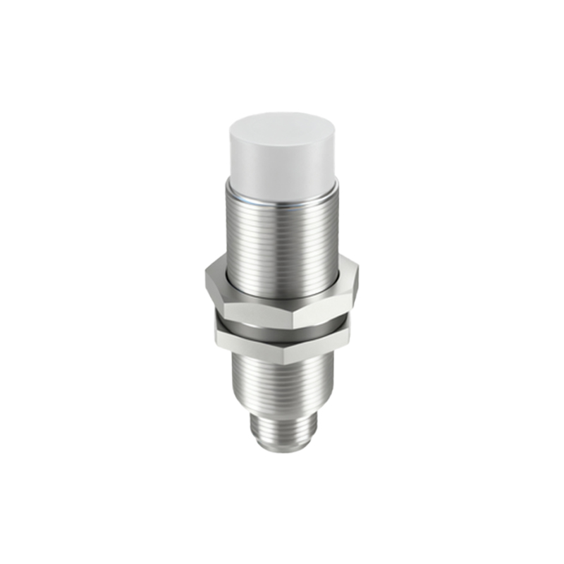
Defining the NPN Output Configuration
The term "NPN" refers to the type of transistor used in the sensor's output switching circuit. In an NPN proximity sensor, the output transistor is an NPN bipolar junction transistor. In this configuration, the load (such as a PLC input, relay coil, or indicator lamp) is connected between the sensor's output wire (black) and the positive DC supply voltage (+V). When the sensor is inactive (no target detected), the output transistor is off, and the output wire is in a high-impedance state, effectively disconnected. Upon detecting a target, the NPN transistor switches on, connecting the output wire to the negative DC supply voltage (0V or common). This action creates a current path from the positive supply, through the load, through the now-activated transistor, and back to the negative supply, thus energizing the load. This is often described as a "sinking" output because the active transistor "sinks" current from the load to the common negative rail.
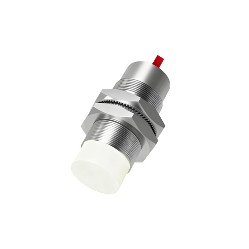
Wiring and Electrical Characteristics
Correct wiring is critical for safe and reliable operation. The standard color coding for 3-wire DC sensors is brown for +V (10-30V DC), blue for 0V (common), and black for the switching output. For an NPN sensor, the black wire is the switched negative. The load must be connected between the black wire and the positive supply. A crucial step often overlooked is connecting a protective flyback diode across the load if it is inductive (like a relay coil). This diode prevents voltage spikes from damaging the sensor's internal transistor when the load is de-energized. Electrically, key specifications include the operating voltage range, switching current capacity (often 100-200mA), leakage current when off (ideally negligible), and voltage drop across the transistor when on (typically less than 1.5V). Understanding these parameters ensures compatibility with the controller's input module, which must be designed to accept a sinking (NPN) signal.
Contrasting NPN and PNP Sensor Types
A common point of confusion is the difference between NPN and PNP sensors. While the internal sensing principle is identical, the output circuitry is opposite. As explained, an NPN sensor sinks current. A PNP sensor, which uses a PNP transistor, sources current. In a PNP configuration, the load is connected between the output wire (black) and the negative/common supply. When active, the PNP transistor connects the output to the positive supply, sourcing current to the load. The choice between NPN and PNP is largely determined by the control system's architecture. Many PLCs and controllers in Europe and Asia are traditionally wired to accept PNP (sourcing) signals. In contrast, NPN (sinking) sensors are historically more common in Japan and are widely used in regions where this convention has been adopted. It is essential to match the sensor type to the input module; connecting an NPN sensor to a PNP-designed input will not function.
Practical Application Considerations
Selecting and applying an NPN 3-wire proximity sensor requires attention to several practical details. First, determine the sensing distance required, noting that the rated operating distance is defined for a standard mild steel target. For other metals, a correction factor must be applied. Second, consider the sensor's housing material (metal or plastic) and shape (barrel, rectangular) based on the installation environment and mounting constraints. Third, ensure the sensor's switching frequency meets or exceeds the required cycle time of the application. Fourth, for harsh environments, specify sensors with appropriate IP (Ingress Protection) ratings for dust and water resistance. Finally, always perform a functional test after installation. Use the sensor's built