Understanding the Fundamentals of Photoelectric Sensing
Photoelectric sensors are ubiquitous in industrial automation, serving as the eyes of countless systems for object detection, positioning, and measurement. Their operation hinges on the emission of a light beam—typically from an LED or laser diode—and the reception of its reflection or interruption by a photodetector. The core principle involves detecting changes in the received light intensity to trigger a switching output. While their primary function is detection, the precise orientation and angular alignment of the sensor relative to the target and background are critical for reliable operation. Incorrect angles can lead to false triggers, missed detections, or reduced sensing range. Therefore, understanding how to properly adjust the sensor's rotational angle is not merely an installation step but a fundamental aspect of system optimization. This adjustment ensures the light path is optimally aligned with the application's specific requirements, whether it's detecting a transparent bottle on a high-speed conveyor or ensuring precise registration marks in printing machinery.
Mechanical Methods for Sensor Angle Adjustment
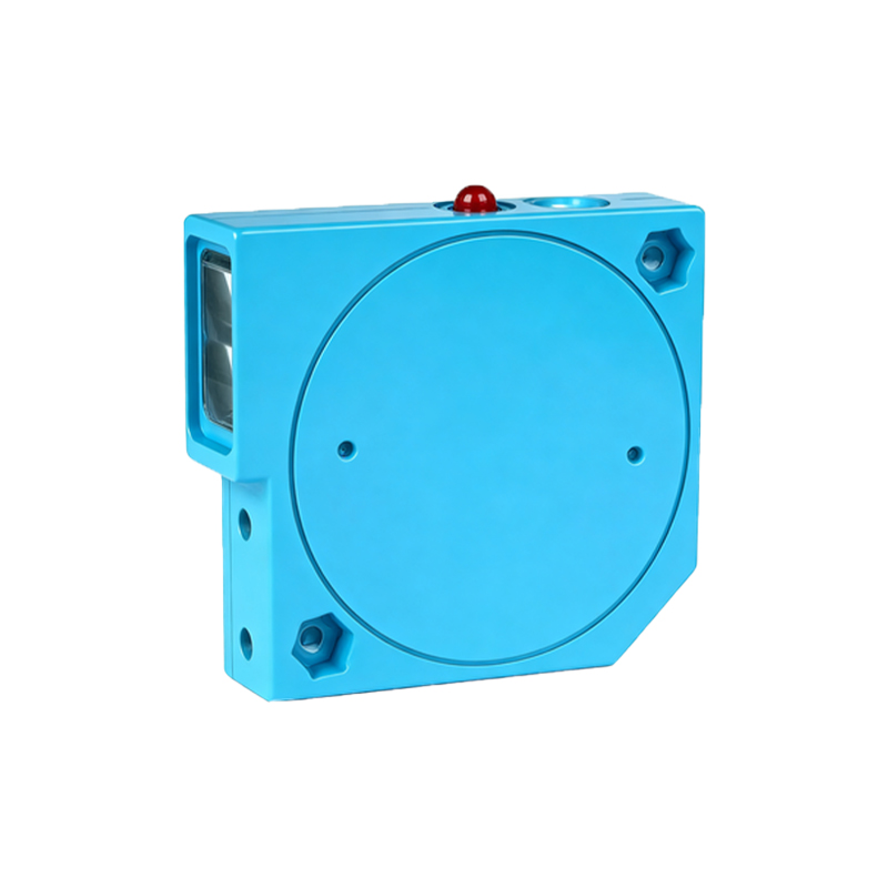
The most direct method for rotating a photoelectric sensor involves its mechanical mounting hardware. Many industrial photoelectric sensors are housed in cylindrical or rectangular bodies designed with integrated mounting threads or brackets that allow for rotational adjustment. For cylindrical sensors, a standard locknut arrangement is common. The sensor body is threaded through a mounting hole in a bracket or machine frame. By loosening the locknut, the engineer can freely rotate the sensor to the desired azimuth and elevation angle before tightening the nut to secure its position. More sophisticated mounting systems include adjustable swivel brackets or gimbal mounts that provide two axes of rotation (pan and tilt). These brackets often feature graduated scales or protractors, enabling precise angular settings and repeatability. When employing mechanical adjustment, it is crucial to consider cable management to prevent strain on the electrical connections during rotation and to ensure the sensor housing does not interfere with other machine components in its new orientation.
Leveraging Built-in Optical Features for Alignment
Modern photoelectric sensors frequently incorporate optical aids to facilitate accurate angular positioning without external tools. A key feature is the visible red or green alignment beam. While the primary sensing beam might be infrared, a coaxial visible light source provides a clear indication of where the sensor is aimed. By observing the visible spot on the target, an engineer can finely rotate the sensor until the beam hits the desired detection point. This is especially useful for aligning opposed-mode (through-beam) sensors, where the emitter and receiver must be perfectly collimated. Some advanced models feature a "teach-in" function or potentiometers for adjusting the sensing window. Although these primarily set sensitivity thresholds, they can indirectly inform angular adjustment. If the sensor signal is weak at the current angle, a minor physical rotation, guided by the live feedback from the teach-in process, can maximize the signal strength, indicating optimal alignment.
The Role of Sensor Type in Angular Configuration
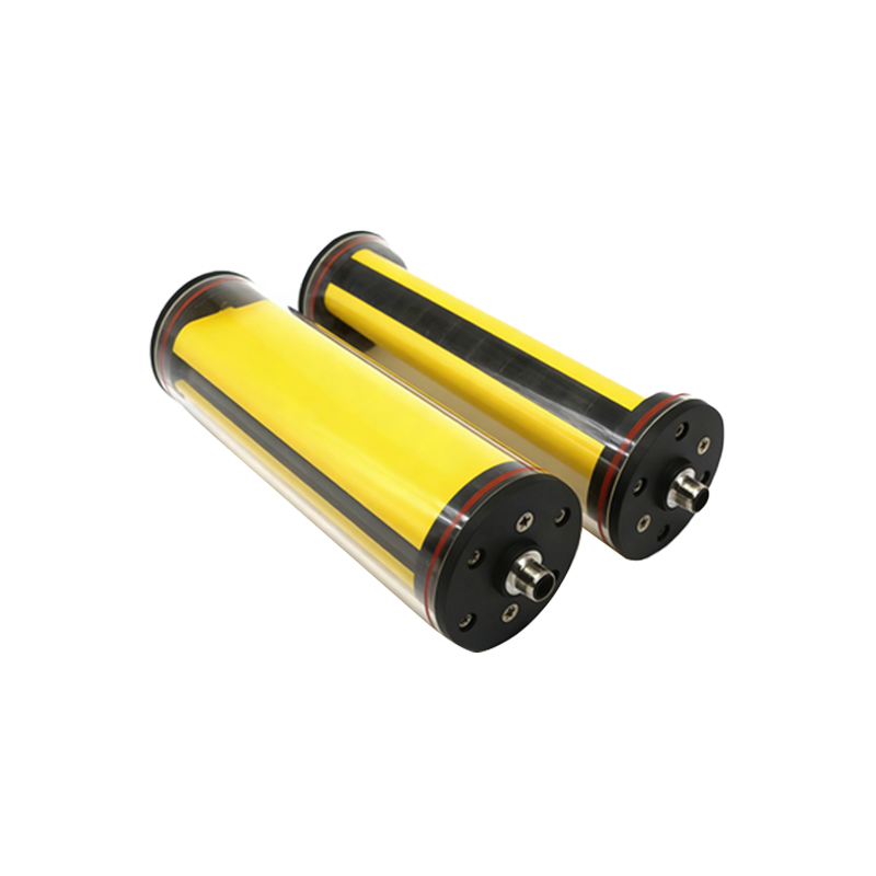
The method and necessity of angle rotation are heavily influenced by the operating mode of the photoelectric sensor. Through-beam sensors, comprising separate emitter and receiver units, require the most precise angular alignment. Both units must be rotated so their optical axes are perfectly parallel and facing each other; even a slight deviation can cause signal loss. Retro-reflective sensors, which bounce light off a reflector, are more forgiving but still require the sensor to be oriented squarely towards the reflector for maximum efficiency. Diffuse (proximity) sensors, which detect light reflected directly from the target, offer the greatest flexibility. Their angle can be adjusted to minimize the influence of a shiny or uneven background. For instance, rotating the sensor slightly so its beam strikes the target at an oblique angle can help distinguish the target from a specular background that might otherwise cause a false reflection.
Application-Specific Angle Optimization Strategies
Optimal sensor angle is dictated by the specific application challenge. For detecting small objects, rotating the sensor to ensure the beam's narrowest cross-section intersects the object improves resolution. On conveyor systems, sensors are often angled to detect the leading edge of a package, avoiding shadows or gaps. When dealing with transparent materials like glass or plastic films, a technique involves rotating both the emitter and receiver (in a through-beam setup) to a non-perpendicular angle (e.g., 45 degrees). This prevents the beam from passing straight through without refraction, instead ensuring it reflects or refracts off the surface to be detected by the receiver. For color mark detection, the angle is critical to standardize the incident light on the mark and the path to the receiver, ensuring consistent contrast reading regardless of material surface variations.
Verification and Calibration Post-Rotation
After physically rotating the photoelectric sensor, verification and calibration are mandatory steps. This involves checking the sensor's output across the entire expected range of target conditions. Use the actual target material and move it through the detection zone. Monitor the sensor's response using its built-in indicator LED or a programmable logic controller (PLC) input status. Ensure the switching is crisp and repeatable. For analog or measuring sensors, verify the output signal corresponds correctly to the target's position or distance at the new angle. Environmental factors like ambient light from windows or overhead lamps can change with sensor orientation; therefore, a final check under normal operating conditions is essential. Document the final angular setting, especially if the mount has a scale, for future maintenance or replication.