Understanding Proximity Switch Sensor Symbols
In electrical and electronic schematics, symbols serve as a universal language, conveying complex component functions through simple graphical representations. The proximity switch sensor symbol is a critical element in this lexicon, especially for automation, control systems, and machinery design. Unlike basic mechanical switches, a proximity switch operates without physical contact, detecting the presence or absence of an object through electromagnetic fields, light, or sound. Its symbol, therefore, must encapsulate this non-contact sensing principle. The foundational symbol often resembles a standard switch symbol—a line interrupted by a gap—but is augmented with distinctive graphical modifiers. These modifiers, typically two parallel lines or a diamond shape adjacent to the switch, explicitly indicate the non-contact, sensing nature of the device. Recognizing this symbol is the first step for any engineer or technician in interpreting a circuit's logic and functionality, forming the basis for system troubleshooting, design, and documentation.
Decoding the Core Symbol and Its Variations
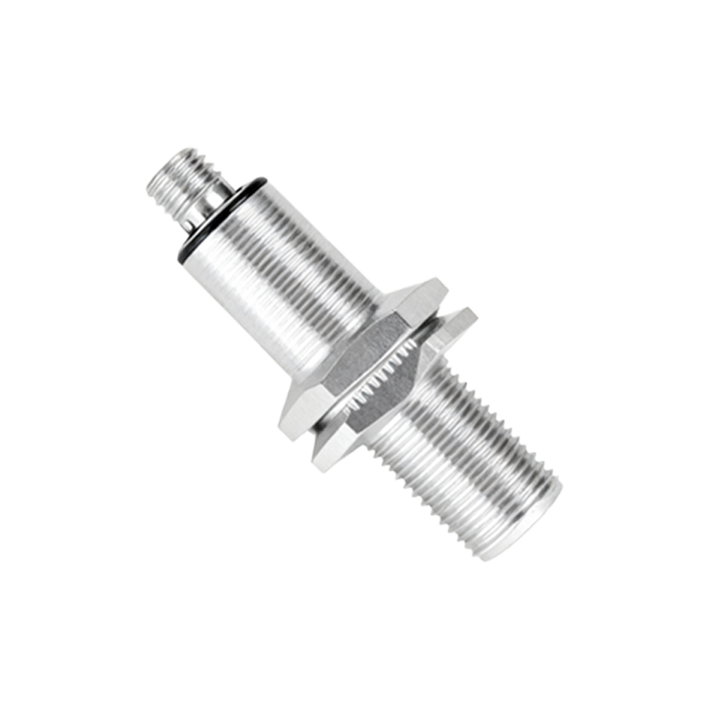
The basic IEC (International Electrotechnical Commission) and ANSI/IEEE (American National Standards Institute/Institute of Electrical and Electronics Engineers) standard symbol for a generic proximity sensor features a square or rectangle representing the sensor body. From this shape, two diagonal lines or a single line with a gap extends, culminating in the standard switch contact symbol. The key identifier is the addition of two short, parallel lines placed perpendicular to the sensing face of the symbol, often enclosed in a circle or diamond. This denotes the active sensing field. Variations arise to specify the sensor type. An inductive proximity sensor symbol, used for detecting metallic objects, may include an inductor coil symbol (a series of loops) within or adjacent to the sensor body. A capacitive sensor symbol, for detecting both metallic and non-metallic materials, might incorporate two parallel plates, representing its capacitive principle. Photoelectric sensor symbols integrate a light emitter (diode symbol with arrows outward) and a receiver (diode symbol with arrows inward), connected to the switch logic.
NO and NC Contact Configurations in Symbols
A crucial aspect of the proximity switch symbol is its depiction of the electrical contact state—Normally Open (NO) or Normally Closed (NC). This defines the default condition of the switch's output contacts when no target is present in the sensing range. A Normally Open (NO) proximity switch symbol shows the contact lines separated. When the sensor detects an object, this contact closes, completing the circuit. In contrast, a Normally Closed (NC) symbol displays the contact lines connected. Detection of an object causes this contact to open, breaking the circuit. The symbol must clearly distinguish between these two states, as they directly determine the control logic. For instance, an NO configuration might be used to activate a machine when a part arrives, while an NC configuration could be used for a safety interlock that stops a machine if a guard is removed. Misinterpreting this part of the symbol can lead to incorrect wiring and potentially hazardous operational failures.
Integration into Ladder Logic Diagrams
In industrial automation, proximity sensors are most frequently encountered in ladder logic diagrams (LLDs). Here, the symbol is simplified to fit the ladder rung format. It is represented as a standard contact symbol (either NO or NC) but is labeled with a unique address or tag, such as "PS1" or "PROX_INPUT." The graphical diamond or parallel lines modifier is often omitted in pure ladder logic for simplicity, but the functional annotation (e.g., "INDUCTIVE," "CAP," or "PHOTO") is critical. The accompanying I/O (Input/Output) list or legend will explicitly define "PS1" as a specific type of proximity sensor. The power of the symbol in this context lies in its logical representation. It shows the engineer how the sensor's state (activated or not) influences the flow of logic to control outputs like motors, solenoids, or pilot lights. Understanding the symbol's place on the ladder rung is essential for programming Programmable Logic Controllers (PLCs) and diagnosing automated sequences.
Importance for System Design and Troubleshooting
Accurate interpretation of proximity switch sensor symbols is non-negotiable for effective system design and maintenance. During the design phase, correctly symbolizing the sensor type and contact configuration ensures the schematic accurately reflects the intended machine behavior, guiding the panel builders and programmers. For troubleshooting, a technician uses the schematic as a map. By identifying the sensor's symbol on the diagram, they can locate its physical counterpart in the machine, understand its normal operating state (NO or NC), and predict the voltage signal that should be present at its terminals under various conditions. For example, if a machine fails to cycle, the technician can trace the logic on the diagram,