Threaded installation remains one of the most common and reliable methods for mounting industrial proximity sensors. This approach ensures secure placement, accurate sensing alignment, and protection against environmental factors such as vibration, moisture, and dust. Proper installation directly impacts sensor performance, longevity, and system safety. This guide outlines key considerations and step-by-step procedures for effective threaded installation.
Before beginning installation, verify the sensor specifications, including thread type, size, and material. Common thread standards include metric (e.g., M8, M12, M18) and NPT (National Pipe Thread). Using mismatched threads can damage the sensor housing or mounting surface, leading to misalignment or failure. Always refer to the manufacturer’s datasheet for exact dimensions and torque ratings.
Prepare the mounting location by ensuring the threaded hole is clean, free of debris, and properly aligned with the target object. Debris or damage in the threads can cause cross-threading, which may strip the threads or compromise the sensor’s seal. If installing in metal, use a thread tap to clean or recut threads if necessary. For added protection in harsh environments, consider applying a mild thread sealant compatible with the sensor material, avoiding sealants that could contaminate the sensing face.
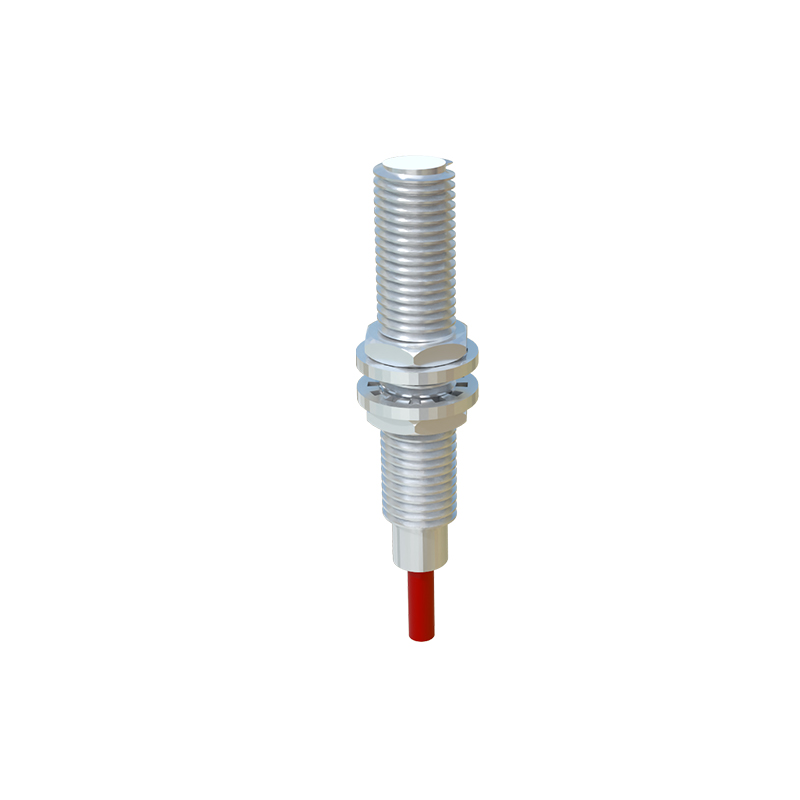
During installation, hand-tighten the sensor first to avoid cross-threading. Rotate it clockwise until it seats fully against the mounting surface. Once hand-tight, use a calibrated torque wrench to apply the recommended torque. Over-tightening can crack the sensor housing or deform threads, while under-tightening may allow movement or leakage. Typical torque values range from 5 to 20 Nm depending on size and material, but always follow manufacturer guidelines.
After securing the sensor, check its orientation relative to the target. The sensing face should be parallel to the target surface and positioned within the specified sensing range. Avoid placing the sensor too close or too far, as this affects accuracy. For inductive sensors, ensure the target material (e.g., steel, aluminum) matches the sensor’s detection capabilities. Adjust the mounting if necessary, but avoid loosening and retightening repeatedly, as this can wear threads.
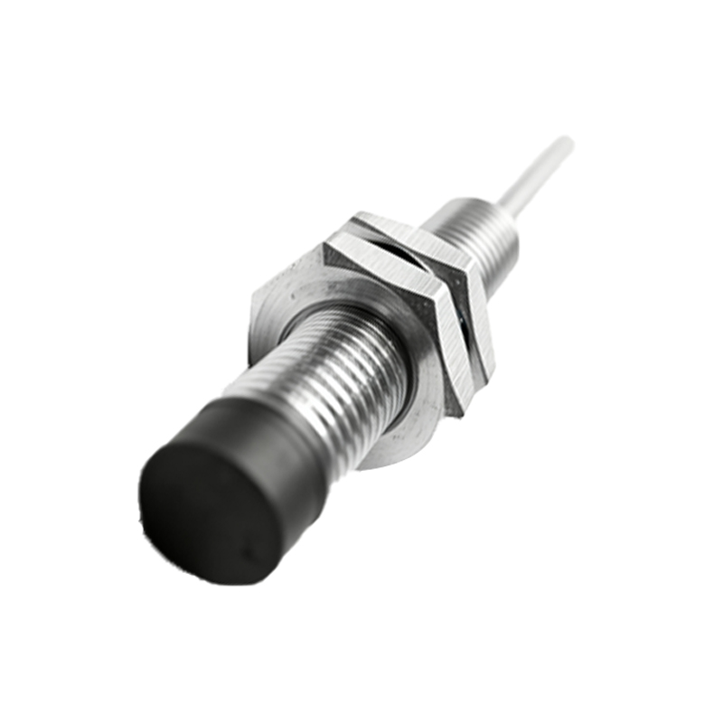
In applications with high vibration, use a lock nut or thread-locking adhesive to prevent loosening over time. For flush-mounted sensors, ensure the sensing face is aligned with the mounting surface to avoid physical damage from passing objects. Non-flush models require a clearance zone around the sensing face—maintain this space as specified.
Finally, conduct functional tests. Power the sensor and observe its response to the target. Verify stability under operational conditions, including temperature extremes or exposure to fluids. Document the installation details, including torque applied and orientation, for future maintenance. Regular inspections should include checking for loose fittings, corrosion, or physical damage.
By following these practices, threaded installation can provide a durable, precise mounting solution that maximizes proximity sensor performance in diverse industrial settings.