Introduction to Landing Gear Proximity Sensing
Landing gear proximity sensors are critical components in modern aviation systems, responsible for providing accurate and reliable position feedback for the landing gear assembly. These sensors detect whether the landing gear is in the fully retracted (up) or fully extended (down) and locked position. This information is vital for the aircraft's flight control computers, cockpit indication systems, and warning systems. The primary function is to ensure pilot awareness and enable automated system responses, directly contributing to flight safety. A failure in this sensing system can lead to erroneous indications, potentially resulting in a gear-up landing or other hazardous situations. Therefore, the design, principle, and reliability of these sensors are paramount.
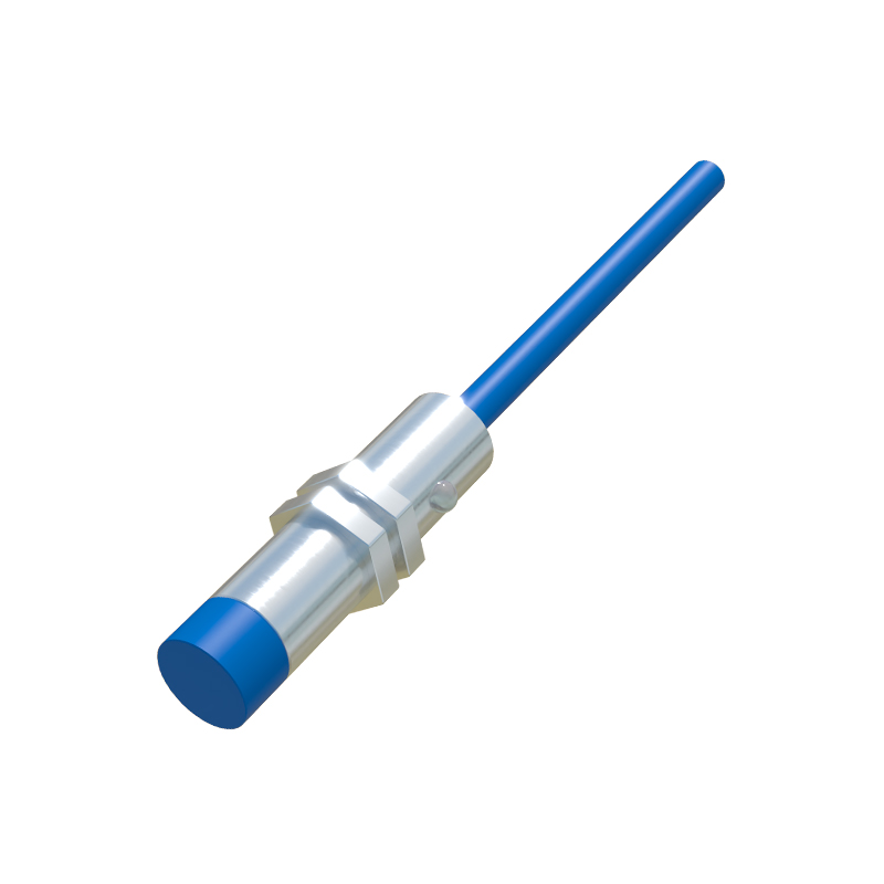
Core Operating Principles
The vast majority of modern landing gear proximity sensors operate on the non-contact inductive or eddy current principle. A typical sensor consists of a coil wound around a ferromagnetic core, which is energized with a high-frequency alternating current. This generates an oscillating electromagnetic field around the sensor's active face. When a metallic target—typically a lobe or flag attached to the landing gear linkage—comes within this field, eddy currents are induced on the target's surface. These eddy currents create their own magnetic field, which opposes the original field from the sensor. This interaction alters the impedance of the coil within the sensor. An integrated electronic circuit, often a Schmitt trigger or a similar oscillator/demodulator circuit, monitors this impedance change. When the shift passes a predefined threshold, the circuit switches its output state, signaling the presence or absence of the target.
Sensor Types and Configurations
Two main configurations are prevalent: normally open (NO) and normally closed (NC), referring to the output state when the target is absent. Differential sensors, offering increased immunity to environmental factors like temperature drift, are also common. The physical packaging is ruggedized to withstand extreme aviation environments, including vibration, shock, wide temperature ranges (-55°C to 125°C+), fluid contamination (hydraulic fluid, Skydrol), and electromagnetic interference. They are typically housed in stainless steel or anodized aluminum bodies with environmentally sealed connectors. Sensors are strategically mounted on the aircraft's airframe, while the target is precisely positioned on a moving part of the landing gear mechanism, ensuring consistent detection at the exact lock points.
Signal Output and Interface
The output from these proximity sensors is typically a simple discrete (binary) signal. Traditional systems use a two-wire AC or DC configuration, where the change in current draw indicates the state change. Modern digital aircraft increasingly utilize three-wire formats (power, ground, signal) providing a solid-state switched voltage output (e.g., 28V DC open collector). This digital signal is fed into the Landing Gear Control and Interface Unit (LGCIU) or directly into the aircraft's central computer systems. Redundancy is a key design feature; multiple sensors are often used for each gear position (e.g., two or three per "down and locked" state) and their outputs are compared via voting logic in the control unit to guard against single-point failures.
System Integration and Safety Features
Integration into the overall landing gear system is complex. The sensor data is used to illuminate cockpit panel lights (green for down and locked, red for unsafe), trigger aural warnings (e.g., "gear not down"), and inhibit certain flight operations. For instance, the aircraft's flap or thrust management systems may use gear-up signals to enable specific performance profiles. Safety features include built-in test (BIT) capabilities, where the control unit can periodically test the sensor circuit for opens or shorts. The physical design often includes mechanical redundancy; the primary sensor may detect a locked over-center linkage, while a secondary sensor verifies the door position or another independent mechanical condition.
Maintenance and Troubleshooting
Maintenance procedures for landing gear proximity sensors involve regular inspections for physical damage, security of mounting, and connector integrity. Functional testing is performed using a metallic target to simulate the gear's movement while monitoring the output signal with a multimeter or specialized aircraft test set. Common failure modes include internal circuit failure due to moisture ingress, broken wires at the connector, and degraded performance from metallic debris buildup on the sensor face. Calibration, in the traditional sense, is not adjustable; the sensing distance is fixed by design. Adjustment is achieved by physically shimming the sensor or the target to achieve the correct air gap specification, which is critical for reliable operation.
Advancements and Future Trends
Technological advancements are leading to more intelligent sensors. These include "smart sensors" with integrated microprocessors that can communicate over digital data buses (like ARINC 429