Introduction to Proximity Switch N8
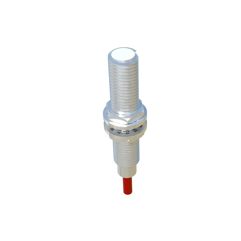
In the realm of industrial automation and electrical control systems, the Proximity Switch N8 stands as a pivotal component for non-contact object detection. This inductive sensor is engineered to detect the presence or absence of metallic objects without any physical contact, thereby ensuring high reliability and longevity in demanding operational environments. The N8 series is renowned for its robust construction, consistent performance, and versatility across various applications, from manufacturing assembly lines to material handling systems. Its design typically incorporates a sensing face, an LED status indicator, and a cable or connector output, all housed in a compact, often cylindrical, metal or polymer body. Understanding its fundamental operating principle—based on generating an electromagnetic field and detecting changes caused by a metallic target—is the first step in leveraging its full potential within any control circuit.
Key Technical Specifications and Operating Principles
The operational efficacy of the Proximity Switch N8 is defined by a set of critical technical parameters. Primarily an inductive type sensor, it generates a high-frequency oscillating electromagnetic field from its active face. When a ferrous or non-ferrous metal target enters this field, eddy currents are induced in the target, causing a dampening of the oscillation amplitude. The sensor's internal circuit detects this change and triggers a solid-state switching output. Key specifications include the sensing distance, often standardized (e.g., 2mm, 4mm, 8mm), which is nominal and can be affected by the target material's properties and size. The operating voltage range is typically DC (10-30V DC) or sometimes AC/DC, with outputs being either NPN (sinking) or PNP (sourcing) transistor configurations. Other vital parameters are the switching frequency (response speed), temperature range, housing material (like nickel-plated brass or stainless steel), and protection class (commonly IP67 for dust and water resistance), ensuring durability in harsh industrial settings.
Wiring and Electrical Integration
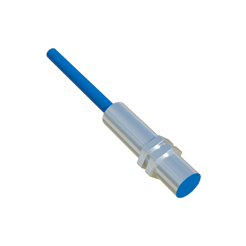
Correct electrical integration is paramount for the reliable operation of the Proximity Switch N8. The standard wiring configuration involves three wires: brown for positive supply voltage (V+), blue for common negative (0V), and black for the switched output signal. For a PNP (sourcing) type, the black wire provides a positive voltage to the load (e.g., a PLC input) when a target is detected. For an NPN (sinking) type, the black wire connects the load to ground upon detection. It is crucial to connect a protective load resistor in series if driving an LED indicator directly. The sensor must be powered within its specified voltage range, and proper shielding of cables is recommended in environments with significant electromagnetic interference. The built-in LED simplifies diagnostics, illuminating when the sensor is powered and often changing state or blinking upon target detection, aiding in setup and troubleshooting.
Application Scenarios and Best Practices
The Proximity Switch N8 finds extensive application in diverse industrial scenarios. Common uses include position sensing for machine tool slides, end-of-travel detection for cylinders, counting metallic parts on a conveyor, and detecting the presence of a workpiece in a machining center. Best practices for installation are critical for optimal performance. The sensor should be mounted securely to avoid vibration-induced errors. Engineers must account for the "effective sensing distance," which can be less than the nominal distance, and ensure that only the specified target material approaches the sensing face. It is also essential to maintain adequate clearance from other metal objects in the environment to prevent false triggering—a practice known as providing sufficient "flush-mounting" or "non-flush" clearance as per the sensor's design. Regular maintenance involves checking for physical damage, buildup of metallic debris on the sensing face, and verifying the stability of electrical connections.
Troubleshooting Common Issues
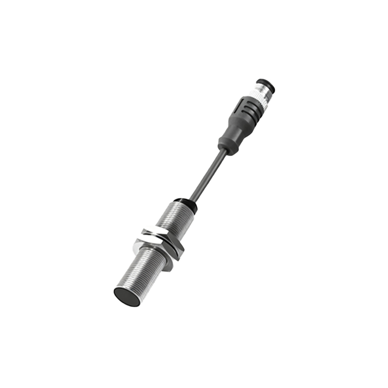
Even with robust design, issues can arise with Proximity Switch N8 units. Common problems include failure to detect a target, intermittent operation, or constant activation. A systematic troubleshooting approach begins with checking the power supply voltage and polarity at the sensor terminals. Verify that the target material, size, and approach speed are within specifications. Inspect the sensing face for contamination and ensure the target is entering the sensing field correctly. Using a multimeter, check the output signal against the expected state. Environmental factors like extreme temperatures, strong magnetic fields, or incompatible chemicals degrading the housing can also cause failures. Often, substituting the sensor with a known-working unit can quickly isolate the problem to either the sensor itself or the external wiring and load.
Comparison with Other Sensor Types and Future Trends
While the inductive Proximity Switch N8 is ideal for metals, understanding its place relative to other technologies is important