Introduction to Photoelectric Sensor Operation
Photoelectric sensors are widely used in industrial automation for detecting the presence, absence, or distance of objects. They operate by emitting a light beam, typically from an LED or laser diode, and then detecting the reflected or interrupted light using a photodetector. A common question among engineers and technicians is whether the light reception component, such as the receiver or photodetector, has a designated positive or negative polarity. Unlike power supply connections, the light reception itself does not inherently have polarity. The photodetector, often a phototransistor or photodiode, converts light intensity into an electrical signal. However, the electronic circuit that processes this signal, including the sensor's output stage, does require correct polarity for power and signal wiring. Misunderstanding this distinction can lead to installation errors or sensor malfunction.
Understanding Photodetector Components
The core of light reception in photoelectric sensors is the photodetector. Common types include photodiodes and phototransistors, which are semiconductor devices. These components generate a current or change resistance when exposed to light, but they do not have a "positive" or "negative" side for light itself. Instead, they have electrical terminals—anode and cathode for photodiodes, or collector and emitter for phototransistors—that must be connected with correct polarity to the sensor's internal circuitry. For instance, a photodiode in reverse bias mode may be used for better response time. The light, as photons, interacts with the semiconductor material, creating electron-hole pairs that produce an electrical signal. This process is polarity-agnostic; light reception efficiency depends on factors like wavelength alignment and intensity, not electrical polarity of the light beam.
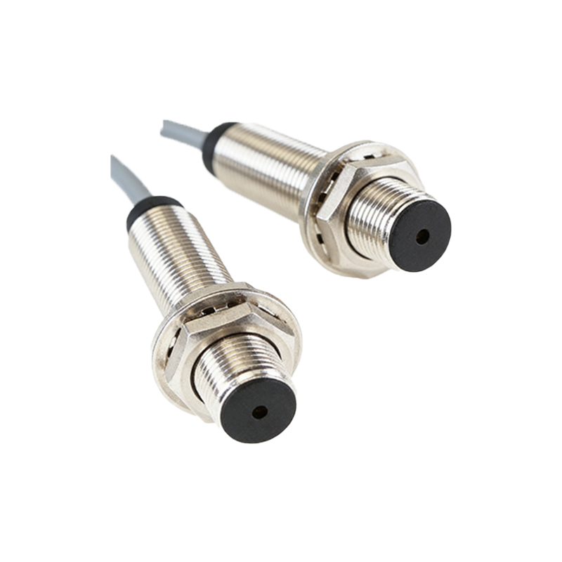
Wiring and Polarity Considerations in Sensor Installation
While light reception lacks polarity, the overall sensor unit requires careful attention to wiring polarity. Most photoelectric sensors have power terminals (e.g., V+ and V- or L+ and L-) that must be connected correctly to avoid damage. Additionally, output types like NPN or PNP transistors or relay outputs have specific polarity requirements for load connections. For example, in a DC sensor, reversing power polarity can cause immediate failure. The receiver circuit, which amplifies and processes the signal from the photodetector, also relies on proper power supply polarity to function. Engineers should always refer to the sensor's datasheet for wiring diagrams. Some sensors include polarity protection circuits, but incorrect wiring may still lead to unreliable operation or no detection signal, even if the light beam is properly aligned.
Differentiating Between Light Source and Receiver Polarity
It's crucial to distinguish between the light source (emitter) and the receiver in photoelectric sensors. The emitter, such as an infrared LED, does have polarity—it must be forward-biased with correct anode and cathode connections to emit light. If the emitter polarity is reversed, no light is produced, and the sensor won't operate. In contrast, the receiver detects light regardless of its polarization, unless using specialized polarized sensors for glare reduction. In reflective or through-beam sensors, the emitter and receiver are separate units, each with their own power and polarity needs. For instance, in a retro-reflective sensor with polarizing filters, the receiver may be designed to detect only light with a specific polarization to avoid false triggers, but this relates to light wave orientation, not electrical polarity of the receiver itself.
Practical Implications for Sensor Selection and Troubleshooting
When selecting or troubleshooting photoelectric sensors, understanding polarity aspects can prevent common issues. First, ensure the sensor's power supply matches the rated voltage and polarity. For the receiver side, check alignment and cleanliness, as obstructions or dirt can affect light reception more than polarity. If a sensor fails, verify wiring before assuming component failure—a multimeter can test for correct voltage at terminals. In advanced applications, like analog or digital sensors with modulated light, the receiver circuit may include phase-sensitive detection, but this doesn't introduce polarity for light reception. Instead, it helps distinguish the signal from ambient light. Always follow manufacturer guidelines, as some sensors may have specific receiver terminal designations (e.g., for shield connections) that impact noise immunity, not light reception polarity.
Conclusion and Best Practices
In summary, photoelectric sensors do not have positive or negative polarity for light reception—the photodetector responds to light irrespective of electrical polarity. However, the sensor's electronic components and wiring require correct polarity for power and outputs. Key best practices include: consulting datasheets for wiring schematics, using shielded cables in noisy environments to protect receiver signals, and regularly maintaining lens cleanliness to ensure optimal light reception. For engineers, focusing on proper installation and environmental factors will enhance sensor reliability more than worrying about light polarity. As technology evolves, sensors with integrated diagnostics may alert users to wiring errors, but the fundamental principle remains: light reception is a physical process, while polarity is an electrical consideration.