Introduction to Photoelectric Sensors in Blood Oxygen Monitors
Photoelectric sensors are the core component of pulse oximeters, responsible for non-invasively measuring blood oxygen saturation (SpO2). These sensors operate on the principle of spectrophotometry, utilizing light-emitting diodes (LEDs) to transmit specific wavelengths of light—typically red (around 660 nm) and infrared (around 940 nm)—through a vascular tissue bed, such as a fingertip or earlobe. A photodetector on the opposite side receives the light that is not absorbed by the tissue. The varying absorption of these two wavelengths by oxygenated hemoglobin (HbO2) and deoxygenated hemoglobin (Hb) allows the device to calculate the SpO2 percentage. The accuracy and reliability of these measurements are fundamentally dependent on the correct electrical and physical connection of the sensor's components. A precise wiring diagram is therefore not merely a technical schematic; it is the blueprint for ensuring patient safety, signal integrity, and device efficacy.
Key Components and Their Electrical Characteristics
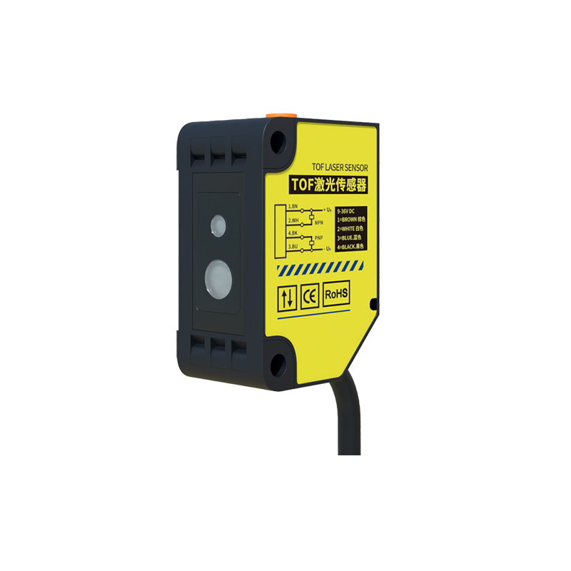
Understanding the wiring diagram begins with identifying the key terminals and their functions. A typical transmission-type sensor (used on fingertips) will have a minimum of four connection points, while a reflectance-type sensor may have a similar or more complex pinout. The primary components are the LED emitters and the photodiode detector. The red and infrared LEDs are usually connected in a common-cathode or common-anode configuration. Their forward voltage (Vf) and drive current are critical parameters; for example, a red LED may have a Vf of 1.8-2.2V, while an infrared LED may be around 1.2-1.6V. The photodiode operates in reverse-bias mode, generating a small photocurrent (in the microamp range) proportional to the received light intensity. This signal is highly susceptible to noise. The wiring diagram must also account for any integrated components within the sensor cable, such as current-limiting resistors for the LEDs or shielding for the signal lines.
Standard Wiring Configurations and Pinouts
While proprietary designs exist, many sensors follow a generalized pinout. For a common four-wire cable with a connector (e.g., a DB9 or a custom medical connector), the typical assignments are: Pin 1: Red LED anode (+); Pin 2: Infrared LED anode (+); Pin 3: Common cathode (-) for both LEDs; Pin 4: Photodiode signal output; Pin 5: Photodiode power supply (reverse bias voltage) or ground. It is crucial to consult the specific sensor's datasheet. The wiring diagram will illustrate these connections from the sensor probe to the main processing board of the oximeter. The diagram uses clear symbols for LEDs, diodes, resistors, and connectors, with distinct net names or wire colors (e.g., Red, IR, GND, SIG) to prevent assembly errors. Proper grounding and separation of the high-current LED drive lines from the low-current photodiode signal line are essential to prevent crosstalk.
Circuit Considerations and Signal Integrity
The wiring diagram is intrinsically linked to the drive and amplification circuits. The LED drive circuit involves a controlled current source, often pulse-width modulated (PWM) to alternate the red and IR lights at high frequency, reducing power consumption and heat. The wiring must ensure minimal voltage drop along the cable to maintain consistent LED brightness. For the photodiode, the diagram leads to a transimpedance amplifier (TIA) circuit, which converts the tiny photocurrent into a measurable voltage. The wiring for this path is critical: it must be as short as possible, properly shielded, and often configured as a twisted pair with its ground to minimize electromagnetic interference (EMI) and 50/60 Hz mains hum. The diagram should specify the use of shielded cable, with the shield grounded at only one end (usually the board end) to avoid ground loops.
Safety and Compliance in Wiring Design
Electrical safety is paramount in medical devices. The wiring diagram must adhere to stringent international standards such as IEC 60601-1. This involves ensuring adequate creepage and clearance distances between conductors in the diagram layout for the PCB, using medically approved insulation materials for cables, and incorporating necessary protections. These protections can include current-limiting resistors in series with the LEDs to prevent overdrive, and protection diodes or TVS (Transient Voltage Suppression) devices on the photodiode input lines to guard against electrostatic discharge (ESD). The diagram should also facilitate the implementation of patient isolation, where the sensor part of the circuit is optically or galvanically isolated from the mains-powered part of the monitor, protecting the patient from potential leakage currents.
Troubleshooting Based on the Wiring Diagram
A correct wiring diagram is an indispensable tool for diagnostics. Common issues like a consistently low SpO2 reading, a failed sensor error, or excessive signal noise can often be traced to wiring faults. Using the diagram, a technician can systematically check for open circuits (broken wires), short circuits (solder bridges or pinched cables), or poor connections at the connector interfaces. For instance, if the infrared LED line is open, the device may default to a reading or fail calibration. By following the diagram and using a multimeter, one can verify continuity, check for correct voltages at the LED pins during operation, and measure the photodiode's output signal. Understanding the expected electrical values at each test point, as derived from the diagram and circuit theory, is key to efficient repair.
Conclusion and Best Practices
In summary, the photoelectric sensor wiring diagram is a vital document that bridges the optical sensing principle with reliable electronic implementation. A well-designed diagram ensures accurate signal acquisition, patient safety, and compliance with medical regulations. Best practices for working with these diagrams include always referencing the latest manufacturer-specific version, using high-quality, medically graded cables and connectors during assembly or repair, and paying meticulous attention to soldering quality and strain relief at connection points. For engineers, a deep understanding of this diagram allows for robust design; for technicians, it enables effective maintenance, ultimately ensuring that the pulse oximeter performs its life-critical function with unwavering reliability.