Understanding Ultra-Long Range Proximity Sensors
Ultra-long range proximity sensors are advanced devices designed to detect objects at distances significantly greater than standard sensors, often exceeding several meters. These sensors utilize technologies such as ultrasonic, laser, or specialized infrared methods to achieve extended detection capabilities. They are commonly applied in industrial automation, security systems, and large-scale material handling where precise long-distance sensing is critical. Unlike short-range sensors, ultra-long range models require careful consideration of environmental factors like temperature, humidity, and interference to maintain accuracy. Their ability to operate reliably over vast areas makes them indispensable in modern engineering projects, enabling automation in warehouses, outdoor monitoring, and complex machinery setups.
Key Components and Wiring Essentials
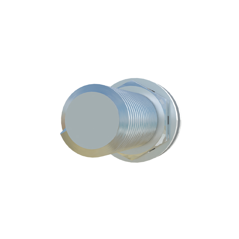
A typical ultra-long range proximity sensor consists of several core components: the sensing element, signal processor, power supply unit, and output module. The wiring diagram for these sensors generally includes connections for power input, ground, output signals, and sometimes auxiliary functions like diagnostics or communication interfaces. Most models operate on DC voltages, such as 12V or 24V, though some industrial versions may support AC power. It is crucial to refer to the manufacturer's datasheet for specific voltage and current ratings to prevent damage. The output can be analog (e.g., 4-20mA or 0-10V) or digital (e.g., NPN/PNP transistor switches), depending on the application needs. Proper wiring ensures stable performance and minimizes false triggers caused by electrical noise or voltage drops.
Step-by-Step Wiring Diagram Analysis
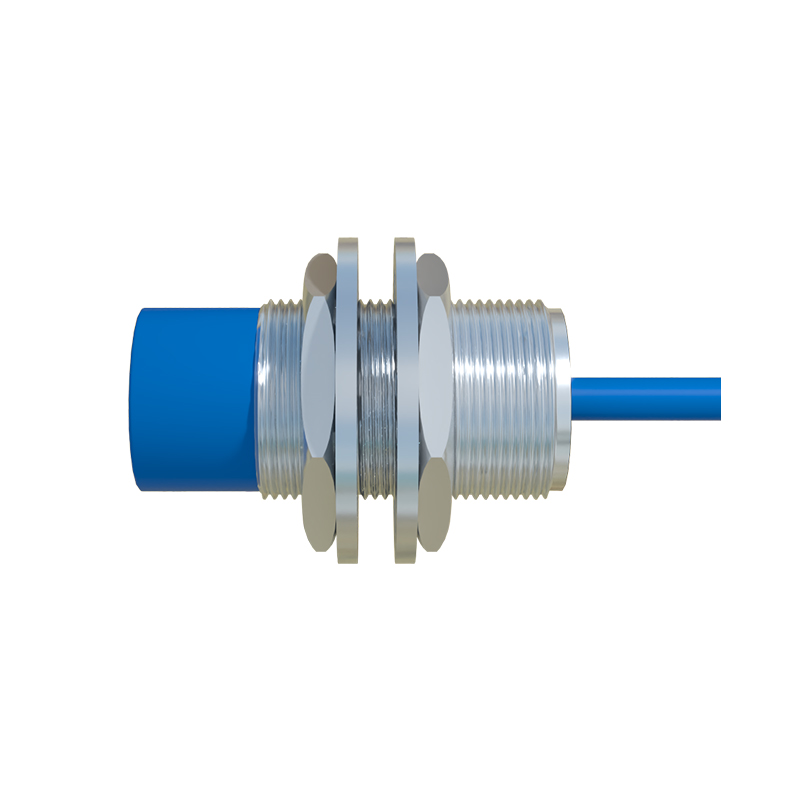
The wiring diagram for an ultra-long range proximity sensor typically outlines connections in a clear schematic format. Start by identifying the power terminals: connect the positive wire from the power source to the V+ terminal and the negative wire to the GND terminal. For sensors with analog outputs, link the output terminal to the input of a PLC or controller, ensuring the signal range matches the device's specifications. In digital output models, the output terminal connects to a load, such as a relay or indicator, with the common terminal tied to the power supply's ground or positive rail based on the sensor type (sourcing or sinking). Always include a protective fuse or circuit breaker in the power line to safeguard against short circuits. Additionally, shielded cables are recommended for long runs to reduce electromagnetic interference, especially in industrial environments with heavy machinery.
Common Wiring Configurations and Examples

Ultra-long range proximity sensors can be wired in various configurations to suit different applications. For instance, in a two-wire setup, the sensor is connected in series with the load and power supply, simplifying installation but limiting output options. Three-wire configurations are more common, offering separate wires for power, ground, and output, which provides greater flexibility and reliability. In complex systems, multiple sensors may be daisy-chained or connected to a network via protocols like IO-Link or Ethernet/IP for centralized control. An example diagram might show a laser-based sensor in a warehouse: power from a 24V DC supply, output to a PLC analog input module, and a separate wire for a diagnostic LED. Always verify polarity and insulation to avoid malfunctions, and test the setup with a multimeter before full operation.
Installation Best Practices and Troubleshooting
To ensure optimal performance, follow installation best practices when wiring ultra-long range proximity sensors. Mount the sensor securely on a stable surface, aligning it properly with the target area to avoid angular misalignment that can reduce effective range. Use conduit or cable glands to protect wires from physical damage and environmental hazards like moisture or dust. During wiring, keep cables away from high-voltage lines or motors to prevent signal interference. For troubleshooting, common issues include no output signal, erratic readings, or reduced detection range. Check connections for loose wires, verify power supply stability, and inspect for obstructions in the sensor's field of view. Consulting the wiring diagram and manufacturer guidelines can help diagnose problems related to incorrect voltage, faulty grounding, or incompatible load resistance.
Applications and Industry Insights
Ultra-long range proximity sensors are widely used across industries due to their versatility. In automotive manufacturing, they monitor vehicle positions on assembly lines over long distances. In agriculture, they assist in automated irrigation systems by detecting equipment movement across fields. Security applications include perimeter monitoring where sensors detect intrusions from afar, triggering alarms or cameras. The wiring diagrams for these scenarios often incorporate additional components like timers, counters, or wireless modules for enhanced functionality. As technology evolves, sensors are becoming more integrated with IoT platforms, allowing remote monitoring via cloud-based systems. Engineers should stay updated on wiring standards, such as IEC 60947, to ensure compliance and safety in global