Introduction to Photoelectric Sensor Fundamentals
Photoelectric sensors operate on the principle of converting light signals into electrical signals. The core components typically include an emitter (light source), a receiver (photodetector), and associated signal processing circuitry. Common light sources are Light Emitting Diodes (LEDs), with infrared being prevalent for its immunity to ambient light interference. The receiver, often a phototransistor or photodiode, detects the presence, absence, or intensity of the emitted light beam. The fundamental operating modes are through-beam, retro-reflective, and diffuse reflective, each suited for specific sensing distances and environmental conditions. Understanding these basics is paramount before embarking on any design experiment, as the choice of mode dictates the subsequent component selection and circuit design.
Experimental Setup and Component Selection
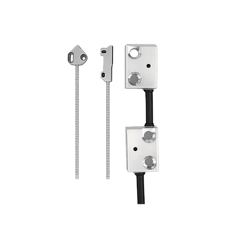
A recent design experiment focused on creating a robust diffuse reflective sensor for object detection at short ranges. The emitter selected was a high-intensity infrared LED with a peak wavelength of 880nm. The receiver was a silicon NPN phototransistor with a matching spectral response. A critical part of the setup was ensuring proper mechanical alignment and housing to minimize crosstalk and ambient light ingress. The circuit was built on a breadboard initially, featuring a current-limiting resistor for the LED and a pull-up resistor for the phototransistor's collector. A variable resistor was incorporated in the emitter circuit to adjust light intensity, a crucial step for calibrating sensitivity. Power was supplied by a stable 5V DC source, and output was monitored using both a multimeter and an oscilloscope to observe signal behavior in real-time.
Circuit Design and Signal Conditioning
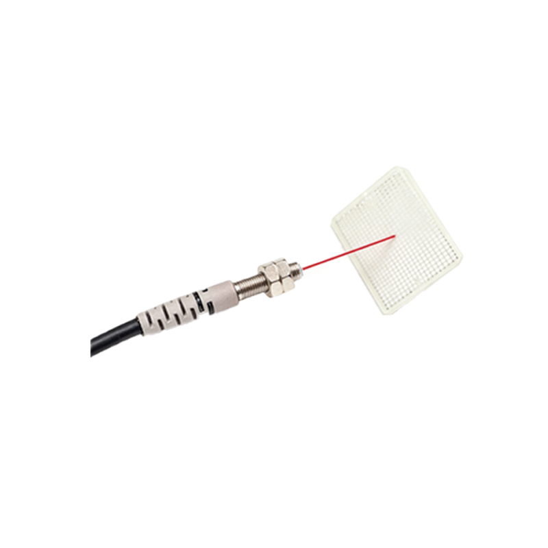
The initial circuit produced an analog output voltage that varied with the amount of reflected light. This raw signal, however, was noisy and susceptible to fluctuations from varying ambient conditions. To create a reliable digital output (ON/OFF), a comparator stage was introduced. A common LM393 comparator IC was used. The voltage from the phototransistor divider network was fed into one input, while a reference voltage, set by a potentiometer, was applied to the other. This allowed for precise adjustment of the sensing threshold. Hysteresis was added using positive feedback with a high-value resistor to prevent output oscillation when the sensed signal was near the threshold. This signal conditioning stage transformed the sensor from a simple detector into a reliable switching device.
Calibration and Sensitivity Adjustment Procedures
Calibration proved to be the most iterative phase of the experiment. The procedure involved placing a standard white test object at the desired sensing distance. The emitter current was first adjusted via its variable resistor to achieve a strong signal return. Then, the reference voltage on the comparator was carefully tuned so that the output reliably switched states (from high to low) precisely when the object entered the sensing field. The hysteresis control was adjusted to ensure a clean switch without chatter. Environmental testing was conducted under different lighting conditions (dark room, fluorescent light, direct sunlight simulation) to validate the setup's stability. This process highlighted that optimal performance is a balance between maximum sensing range and immunity to false triggers.
Performance Analysis and Observed Challenges
The finalized sensor demonstrated reliable detection of non-shiny objects up to 15cm. The digital output provided a clean, fast response suitable for interfacing with microcontrollers or PLCs. Key performance metrics logged included response time (less than 2ms), repeatability, and supply voltage tolerance. Several challenges were encountered and addressed. Ambient infrared light from other sources was a significant issue, partially mitigated by using a modulated light source and corresponding demodulating circuit in a more advanced iteration. Detection of dark or absorbent objects required increased emitter power or a more sensitive receiver. Lens design for the emitter and receiver, though not deeply explored in this basic experiment, was identified as a critical factor for focusing light and increasing range and precision.
Practical Applications and Design Recommendations
The diffuse reflective sensor designed in this experiment has direct applications in industrial automation for object counting, bottle cap detection, and level sensing. Based on the experimental findings, several design recommendations are proposed. Always shield the sensor assembly to block ambient light. Use modulated IR signals with synchronous detection for environments with high optical noise. Incorporate temperature compensation in the design if operating over a wide temperature range, as semiconductor parameters drift. For long-term reliability, derate component operating values and protect the circuit from voltage transients. Finally, prototype testing under real-world conditions, not just ideal lab settings, is non-negotiable for a robust final product. This experiment underscores that successful photoelectric sensor design is a systematic integration of optical, electronic, and mechanical engineering principles.