Introduction to Magnetic Proximity Sensors
Magnetic proximity sensors are fundamental components in modern industrial automation and electrical systems. These devices detect the presence or absence of a magnetic field, typically generated by a moving target such as a gear tooth, cam, or most relevantly for this discussion, the magnetic field surrounding a current-carrying conductor. Unlike physical contact switches, they offer non-contact detection, leading to enhanced reliability, longer service life, and the ability to operate in harsh environments. Their core function is to translate a magnetic stimulus into a clear, usable electrical signal, making them indispensable for monitoring, control, and safety applications across various sectors, from manufacturing to energy distribution.
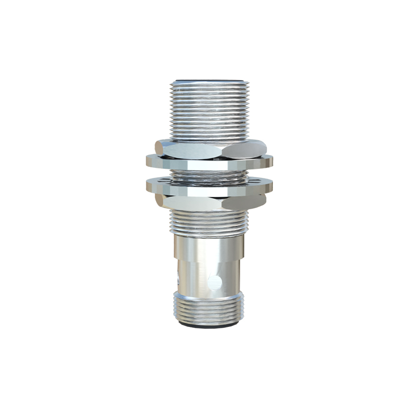
The Core Principle: Hall Effect and Magnetoresistance
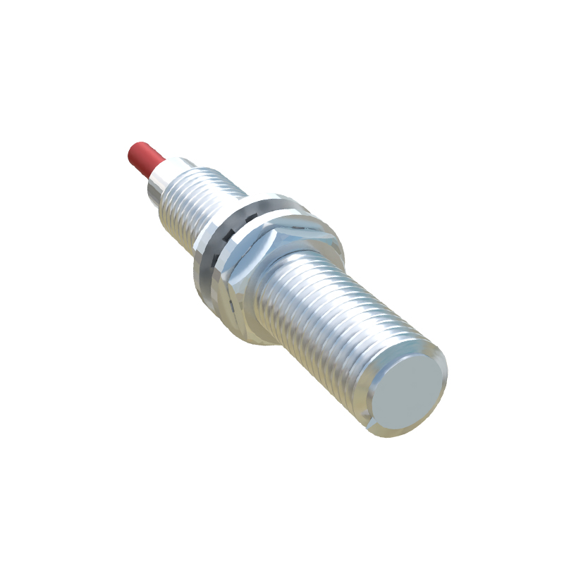
The operation of most current-sensing magnetic proximity sensors is based on one of two primary physical phenomena: the Hall effect or magnetoresistance. The Hall effect, discovered by Edwin Hall in 1879, occurs when a current-carrying conductor is placed in a perpendicular magnetic field. This field exerts a force on the moving charge carriers, deflecting them to one side of the conductor and creating a measurable voltage difference, known as the Hall voltage, across it. This voltage is directly proportional to the strength of the applied magnetic field. In a sensor, a semiconductor Hall element generates this signal. Alternatively, magnetoresistive sensors utilize materials that change their electrical resistance in the presence of a magnetic field. This change in resistance can be measured within a Wheatstone bridge circuit to produce an output signal corresponding to the magnetic field intensity.
Detecting Current via Magnetic Fields
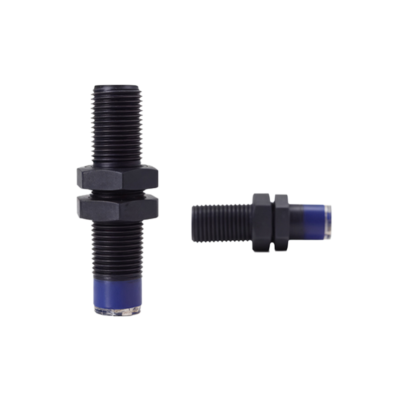
A fundamental law of electromagnetism, Ampère's circuital law, states that an electric current generates a concentric magnetic field around the conductor. The strength of this magnetic field is directly proportional to the magnitude of the current. A magnetic proximity sensor designed for current detection is positioned such that it can sense this generated field. It does not require direct electrical connection to the current-carrying conductor, providing inherent galvanic isolation—a critical safety and performance advantage. The sensor's sensitive element (Hall or magnetoresistive) responds to the magnetic flux density. By calibrating the sensor, the output signal (voltage, current, or a digital pulse) becomes a precise representation of the primary current, enabling functions like overload detection, current monitoring, and energy metering.
Sensor Types and Configurations
For current sensing, these sensors are often integrated into specific form factors. Open-loop sensors place the conductor through a magnetic core's aperture, concentrating the field onto the sensing element. They are simple and cost-effective for measuring large currents. Closed-loop or "compensated" sensors use a feedback coil wound on the same core. The sensor drives a current through this coil to create a magnetic field that nullifies the field from the primary conductor. The compensation current is the direct, highly linear output signal, offering superior accuracy and response time. Furthermore, sensors can be differentiated by output type: analog sensors provide a continuous voltage or current output proportional to the measured field/current, while digital (switch-type) sensors provide a discrete ON/OFF signal when the current exceeds a predefined threshold.
Key Performance Characteristics
Selecting the appropriate magnetic proximity sensor for a current-sensing application requires understanding several key parameters. Sensitivity defines the smallest change in magnetic field or current the sensor can detect. Measurement range specifies the minimum and maximum current values the sensor can accurately measure. Linearity indicates how consistently the output signal follows the input current across the entire range. Bandwidth or frequency response determines the sensor's ability to track rapid changes in current, crucial for monitoring AC systems or switching loads. Other vital factors include operating temperature range, response time, power supply requirements, and the degree of protection against environmental factors like dust and moisture (IP rating).
Common Industrial Applications
The applications for current-sensing magnetic proximity sensors are vast. In motor control, they provide essential feedback for overload protection and speed regulation by monitoring phase currents. Within power supplies and inverters, they enable precise current control and fault detection. They are used in energy management systems to monitor consumption in buildings and industrial processes. Battery management systems in electric vehicles and renewable energy storage rely on them for state-of-charge estimation and cell balancing. Furthermore, they serve as non-contact safety interlocks, ensuring machinery only operates when current is flowing correctly, preventing accidents.
Advantages and Limitations
The primary advantages of these sensors are their non-contact nature, which eliminates mechanical wear and allows for high-speed detection, and their galvanic isolation, which protects control circuitry from high-voltage transients. They are generally robust, have long lifetimes, and can measure very high currents without the power losses