Introduction to Proximity Sensing Technology
Proximity sensors are fundamental components in modern industrial automation, providing non-contact detection of metallic or non-metallic objects. Among the various configurations available, the normally open (NO) two-wire sensor represents a widely adopted and efficient design. This type of sensor integrates seamlessly into control circuits, offering a simplified wiring solution that reduces installation time and potential points of failure. Its operation is based on the principle of detecting changes in an electromagnetic field or capacitive coupling caused by a target object entering its sensing range. The two-wire design is particularly favored for its straightforward integration, as it connects similarly to a traditional mechanical switch but with the enhanced durability and speed of solid-state electronics. Understanding its operational characteristics, wiring methodology, and application considerations is crucial for engineers designing robust and reliable control systems.
Operating Principle of Two-Wire NO Sensors
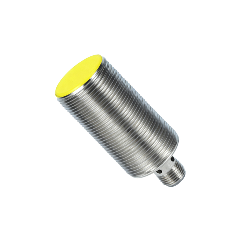
A normally open two-wire proximity sensor operates in a de-energized state when no target is present. In this state, the internal switching element (typically a transistor) is off, presenting a high impedance between its two wires. When a valid target enters the predefined sensing range, the sensor's oscillator circuit is damped or a capacitive balance is shifted, triggering the internal electronics to change state. This action turns the switching element on, effectively closing the circuit and allowing current to flow. The sensor itself requires a small amount of this operating current, known as the residual current or leakage current, to power its internal circuitry even when in the "off" state. This is a key distinction from three-wire sensors and a critical factor in system design. The switching action is fast, wear-free, and capable of handling high cycle rates, making it ideal for repetitive industrial processes.
Wiring and Circuit Integration
Integrating a two-wire NO sensor into a control system is notably simple. The two wires are connected in series with the load (such as a PLC input, relay coil, or indicator lamp) and the power supply. One wire connects to the positive DC voltage or one side of an AC supply, while the other wire connects to the load. The load is then connected back to the negative DC or the other AC terminal, completing the circuit. It is vital to observe the sensor's voltage specifications (e.g., 10-30V DC or 20-250V AC) and ensure the load's impedance is sufficient to limit the current below the sensor's maximum rating. A crucial consideration is the residual current. When the sensor is off, this small current (usually a few milliamps) still flows. The connected load must have a minimum current requirement higher than this residual value; otherwise, it may falsely energize or "glow" when the sensor is supposed to be off. A bleeder resistor is often added in parallel with the load to mitigate this issue.
Key Advantages and Benefits
The primary advantage of the two-wire normally open configuration is its installation simplicity. With only two wires to connect, it reduces material costs, minimizes wiring errors, and saves valuable panel space. This design also offers enhanced safety in certain applications, as the switching element physically breaks the current path to the load. They are highly resistant to vibration, contamination, and environmental factors like moisture or oil when properly housed. Furthermore, their compatibility with both AC and DC power supplies (depending on the model) provides flexibility in retrofitting older systems or designing new ones. The solid-state nature ensures a long operational life with millions of switching cycles, significantly outperforming mechanical limit switches in demanding environments. This reliability translates to reduced maintenance downtime and lower total cost of ownership.
Critical Application Considerations
Successful deployment requires careful attention to several parameters. First, the sensing range must be selected with a safety margin, typically 70-80% of the rated nominal range, to account for temperature fluctuations, target material variations, and mechanical tolerances. The load current must fall between the sensor's minimum operating current (to ensure reliable switching) and its maximum current rating. For inductive loads like relay coils, a protective circuit (such as a flyback diode for DC or a surge suppressor for AC) is recommended to protect the sensor's output transistor from voltage spikes. Environmental factors are also paramount; sensors should be selected with appropriate ingress protection (IP) ratings for dust and water resistance and correct housing materials for corrosive atmospheres. Finally, engineers must consider the sensor's response time and switching frequency to ensure it can keep pace with the application's speed requirements without missing detection events.
Comparison with Alternative Sensor Types
It is instructive to compare the two-wire NO sensor with other common types. The three-wire sensor (PNP or NPN) has