Introduction to 4-Wire Photoelectric Sensors
A 4-wire photoelectric sensor is a versatile and widely used device in industrial automation for detecting the presence, absence, or position of objects without physical contact. Unlike simpler 2-wire sensors that are directly integrated into the power loop, or 3-wire sensors that have a separate signal output, the 4-wire configuration offers distinct advantages. It typically includes two wires dedicated to the power supply and two wires for the output signal, allowing for a clear separation between the sensor's operational power and its switching function. This design enables the use of both a Normally Open (NO) and a Normally Closed (NC) output contact from a single device, providing greater flexibility in control logic design. Understanding the precise wiring definition is crucial for ensuring reliable operation, safety, and optimal performance in applications ranging from packaging and material handling to assembly line monitoring and safety interlocks.
Standard Wire Color Coding and Definitions
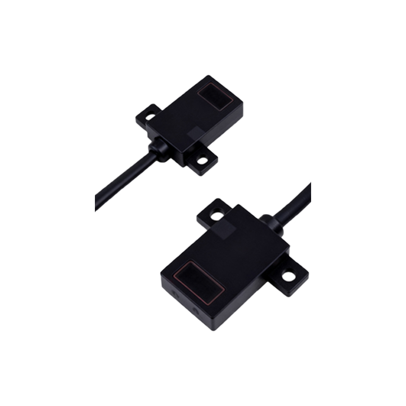
While standards can vary slightly by manufacturer and region, a common and widely accepted color code for DC-powered 4-wire photoelectric sensors is as follows. The Brown wire is universally designated as the positive supply voltage terminal (+V). The Blue wire is consistently used for the common negative or 0V supply terminal. The remaining two wires, typically Black and White, are dedicated to the output signals. The Black wire usually serves as the Normally Open (NO) output contact. In its default state (no object detected), this circuit is open. When the sensor detects a target object, it closes this contact, allowing current to flow. Conversely, the White wire is commonly assigned as the Normally Closed (NC) output contact. This circuit is closed in the default state and opens upon detection. This standardized coloring provides a critical visual guide for electricians and technicians during installation and troubleshooting, reducing the risk of wiring errors.
Detailed Wiring Procedure and Circuit Integration
To correctly wire a 4-wire DC sensor, begin by connecting the power supply wires. Connect the Brown wire to the positive DC voltage source (e.g., +24VDC) and the Blue wire to the DC common or ground. It is imperative to verify the sensor's voltage rating (commonly 10-30VDC) against your power supply. Next, integrate the output wires into your control circuit. The Black (NO) and White (NC) wires are connected to the load you wish to control, such as a programmable logic controller (PLC) input, a relay coil, or an indicator lamp. For example, to use the NO output, you would connect the Black wire to one side of your PLC input card and connect the other side of that input to the positive supply. The Blue wire is often shared as the common return for the outputs. A critical step is to always connect a protective diode (flyback diode) in reverse parallel across inductive loads like relay coils to suppress voltage spikes that can damage the sensor's solid-state switching elements.
Output Types: NPN vs. PNP Sinking and Sourcing
The functionality of the Black and White output wires is fundamentally defined by the sensor's transistor output type: NPN or PNP. This is a paramount concept in sensor wiring. An NPN sensor provides a "sinking" output. In this configuration, when the output is active (e.g., the NO contact closes), it connects the load to the common negative (Blue wire). The load must be connected between the positive supply and the sensor's output wire. A PNP sensor provides a "sourcing" output. When active, it connects the load to the positive supply (Brown wire), and the load must be connected between the output wire and the common negative. The physical wiring of the Brown, Blue, Black, and White wires remains the same, but the electrical behavior and the required load connection are opposite. Selecting the correct type (NPN or PNP) is essential for compatibility with your controller's input module, which is typically designed to accept either sinking or sourcing signals.
Common Applications and Configuration Scenarios
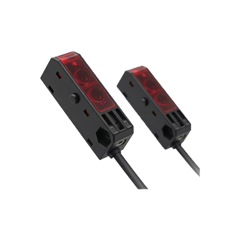
The dual NO/NC capability of 4-wire sensors makes them exceptionally useful in complex control schemes. A typical application is in safety or monitoring circuits where a "fail-safe" condition is required. For instance, an NC output can be used in a safety beam application. Under normal, safe conditions (beam uninterrupted), the NC circuit is closed, keeping a safety relay energized. If the beam is broken (object detected), the NC circuit opens, de-energizing the relay and triggering a machine stop. Simultaneously, the NO output could be used to trigger a visual alarm or a counter. Another common scenario is in bi-directional production lines where the detection of an object needs to trigger different actions depending on the direction of travel. The logic can be programmed in the PLC to interpret the state of both the NO and NC contacts to determine object presence and, by sequence, its direction.
Troubleshooting and Best Practices
Proper wiring is the foundation of reliable sensor operation. Common issues include incorrect voltage application, mixing up NPN and PNP load wiring, or misidentifying the output wires. Always consult the manufacturer's datasheet for the definitive wiring diagram, as color codes, while common, are not an absolute standard. Use a multimeter to verify voltages and continuity. Ensure all connections are secure and protected from vibration. For long cable runs, consider using shielded cable to prevent electrical noise interference, and ground the shield at only one end. Implement proper circuit protection with fuses or circuit breakers. During installation, temporarily secure the wiring and perform a full functional test with the target object before finalizing the setup. Regularly inspect connections for corrosion or damage as part of a preventive maintenance routine to ensure long-term, fault-free operation of your automation system.