Introduction to Inverter-Based Motor Control
In modern industrial automation, precise motor speed control is paramount for efficiency, energy savings, and process optimization. Traditional methods often rely on mechanical feedback or simple voltage regulation, which lack precision and responsiveness. The integration of photoelectric sensors with variable frequency drives (VFDs), commonly known as inverters, presents a sophisticated solution. This system enables dynamic, real-time adjustment of motor speed based on physical conditions detected in the production line, such as the presence, position, or count of objects. The core principle involves the photoelectric sensor acting as the system's eyes, sending discrete or analog signals to the inverter, which then processes this input to modulate the output frequency and voltage supplied to the AC motor, thereby controlling its rotational speed.
Fundamentals of Photoelectric Sensors
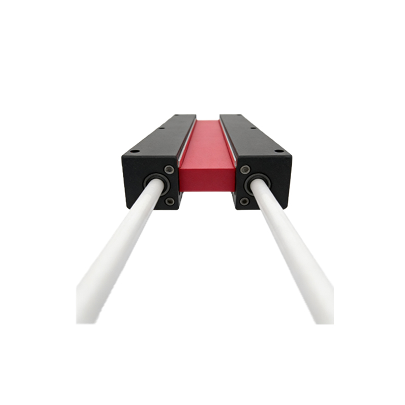
Photoelectric sensors are non-contact devices that detect objects, distances, or changes in surface conditions using a light transmitter and a receiver. They operate primarily in three modes: through-beam, retro-reflective, and diffuse reflective. Through-beam sensors offer the longest sensing range and highest reliability, with separate emitter and receiver units. Retro-reflective types use a reflector to bounce light back to a combined unit, while diffuse sensors detect light reflected directly from the target object. For motor speed control applications, the choice depends on the required precision, environmental conditions, and the nature of the target. These sensors provide critical binary (on/off) or analog (proportional) signals that form the input data layer for the inverter's control logic.
Inverter Functionality and Speed Regulation
An inverter is a power electronic device that converts fixed-frequency, fixed-voltage AC power to variable-frequency, variable-voltage AC output. The speed of an AC induction motor is directly proportional to the frequency of the power supply (N = 120f/P). By altering the output frequency (f), the inverter precisely controls the motor speed (N). Modern inverters are equipped with programmable logic controllers, multiple digital and analog input/output terminals, and sophisticated communication protocols. They can accept signals from external devices like photoelectric sensors and execute pre-programmed responses, such as ramping the motor up to a high speed or down to a low speed, based on the received signal state or value.
System Integration and Wiring Configuration
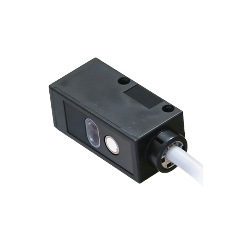
Integrating a photoelectric sensor with an inverter requires careful planning of the electrical interface. Typically, the sensor's output signal is connected to one of the inverter's digital or analog input terminals. For simple on/off control, a digital (PNP or NPN) output from the sensor is wired to a digital input on the inverter. The inverter is then programmed to associate a specific frequency command (e.g., 50 Hz for high speed, 10 Hz for low speed) with the activation of that input. For more nuanced control, an analog sensor output (0-10V or 4-20mA) can be connected to an analog input, allowing for continuous, proportional speed adjustment based on the sensed parameter, such as distance or light intensity. Proper shielding, grounding, and adherence to EMI/RFI guidelines are crucial to prevent signal interference.
Programming the Inverter for Sensor Input
The intelligence of the system lies in the inverter's parameter settings. After physical wiring, key parameters must be configured. These typically include assigning the function of the input terminal (e.g., "Multi-function Digital Input 1" set to "External Fault" or "Speed Command Selection"), setting the acceleration/deceleration ramps (to prevent mechanical shock), and defining the target frequencies for different commands. For instance, a common setup might be: when the sensor detects an object (input ON), the inverter runs the motor at a preset high speed; when no object is present (input OFF), it switches to a low-speed or creep-speed mode. Advanced programming may involve logic functions within the inverter to handle multiple sensor inputs for complex sequencing.
Practical Application Examples
A classic application is in conveyor belt systems. A photoelectric sensor placed at the loading station detects the arrival of a package. Upon detection, it signals the inverter to run the conveyor motor at high speed for rapid transport. A second sensor at the unloading station, upon detecting the package, signals the inverter to slow down or stop the motor for precise positioning. In packaging machinery, a sensor counting items on a line can signal the inverter to increase motor speed if the item count is low (to catch up) or decrease speed if the count is high (to prevent jamming). This closed-loop control enhances throughput and reduces waste.
Advantages and Benefits of the System
The combination offers significant advantages. It enables fully automated, responsive speed control without manual intervention, leading to higher productivity. Energy efficiency is greatly improved, as motors run at optimal speeds only when needed, reducing power consumption. It minimizes mechanical wear and tear on both the motor and driven equipment by enabling smooth acceleration and deceleration. The system improves process consistency and product quality through precise timing and positioning. Furthermore, it offers flexibility; changes in the process can be accommodated by simply reprogramming the inverter or repositioning sensors, rather than undertaking costly mechanical modifications.
Troubleshooting and Maintenance Tips
Reliable operation requires regular maintenance. Common issues include sensor misalignment, lens contamination (dust, oil), which reduces sensing reliability, and electrical noise causing erratic inverter behavior. Regularly clean sensor lenses and check alignment. Verify the sensor's output signal with a multimeter or the inverter's input status indicators. Ensure all connections are tight and cables are undamaged. Within the inverter, monitor parameters for fault codes related to input signals or overloads. Periodically check that the programmed acceleration/deceleration times are still suitable for the mechanical load to prevent trips. Keeping firmware updated can also resolve compatibility issues.
Future Trends and Conclusion
The future of motor control with sensors and inverters is leaning towards greater connectivity and intelligence. The integration of Industrial Internet of Things (IIoT) protocols allows these systems to feed data into centralized monitoring platforms for predictive maintenance and analytics. Smart sensors with integrated logic and IO-Link communication can provide detailed diagnostic information directly to the inverter. Furthermore, advancements in inverter technology, such as built-in PLC functionality and more sophisticated motion control algorithms, will simplify system architecture and enable even more complex, multi-axis coordinated control. In conclusion, using photoelectric sensors to command inverter-based motor speed is a proven, efficient, and adaptable strategy that forms a cornerstone of smart, energy-conscious industrial automation, driving operational excellence across countless applications.