Understanding Photoelectric Sensor Fundamentals
Photoelectric sensors are pivotal components in automated sorting systems, enabling non-contact detection of objects based on light beam interruption or reflection. These sensors typically consist of an emitter, which projects a light beam (often infrared, visible red, or laser), and a receiver that detects changes in the light pattern. In sorting applications, they are used to identify package presence, size, position, and sometimes color or reflectivity, triggering downstream actions like diverting, labeling, or counting. The core principle involves the sensor generating an electrical output signal when the light path is altered by an object. This signal is then processed by a Programmable Logic Controller (PLC) or other control unit to coordinate the mechanical sorting actuators. Selecting the correct sensor type—diffuse, retro-reflective, or through-beam—is the first critical step, as each has distinct wiring and installation requirements based on the sorting environment's range, object characteristics, and ambient light conditions.
Wiring Configurations and Electrical Standards
Proper wiring is essential for reliable sensor operation and system safety. Photoelectric sensors generally have three or four wires, corresponding to power supply, output, and ground. Common configurations include NPN (sinking) and PNP (sourcing) outputs, which define how the sensor switches the load relative to the power supply. In NPN wiring, the output acts as a switch to ground, commonly used in Asian and European markets, while PNP wiring switches the positive voltage, prevalent in North America. The power supply voltage typically ranges from 10-30 VDC, aligning with industrial control standards. Wiring must adhere to local electrical codes, such as NEC or IEC standards, ensuring proper insulation, cable routing away from high-voltage lines to prevent interference, and use of shielded cables in electrically noisy environments. Color-coding follows international conventions: brown for positive (+V), blue for negative (0V), black for output signal, and white for auxiliary functions like timer settings. Incorrect wiring can lead to sensor damage, erratic behavior, or safety hazards.
Step-by-Step Wiring Procedure for Sorting Systems
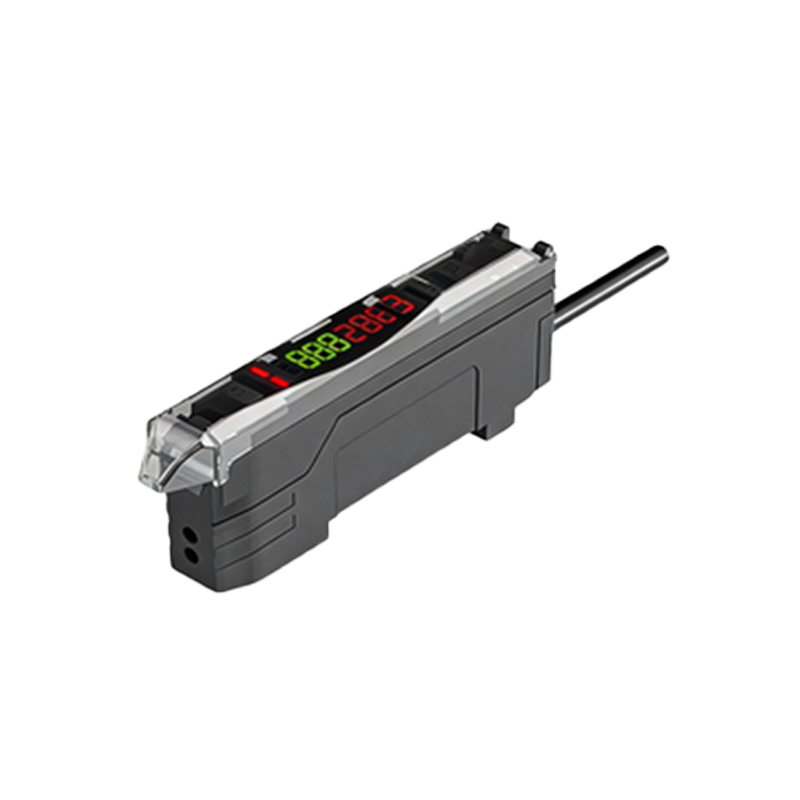
Begin by de-energizing the control panel to prevent electrical shock. Mount the sensor securely on the sorting line frame, aligning the emitter and receiver for through-beam types, or positioning diffuse sensors at the correct angle and distance. For wiring, first connect the power leads: attach the brown wire to the positive DC terminal (e.g., +24V) and the blue wire to the negative or ground terminal. Next, connect the output wire (black) to the PLC input module or relay coil. If using a four-wire sensor with a complementary output, the white wire may connect to a separate control input. Ensure all connections are tight using appropriate terminal blocks or connectors. For through-beam sensors, wire the emitter and receiver separately to the same power source, verifying polarity. After wiring, apply power and test with a sample object; adjust sensitivity potentiometers if available to fine-tune detection, avoiding false triggers from background interference. Document the wiring diagram for future maintenance.
Integration with Control Systems and Troubleshooting
In automated sorting, sensors interface with PLCs, which monitor their signals to activate sorters, conveyors, or reject arms. Wiring the sensor output to the PLC requires matching the voltage levels and input type (sinking or sourcing). Use interposing relays if the sensor output current is insufficient for the PLC input. Common issues include misalignment due to vibration, lens contamination from dust, electrical noise from motors, or wiring faults like loose connections or short circuits. Troubleshooting involves checking power with a multimeter, verifying light beam alignment using the sensor's indicator LED, and inspecting for environmental obstructions. Regular maintenance, such as cleaning lenses and tightening connections, minimizes downtime. For complex systems, implementing diagnostic feedback via networked sensors (e.g., IO-Link) can provide real-time status monitoring, enhancing reliability.
Best Practices for Optimal Performance
To ensure long-term accuracy in sorting applications, follow industry best practices. Select sensors with appropriate sensing ranges and response times for high-speed lines. Use conduit or cable carriers to protect wires from mechanical wear. Implement redundancy for critical detection points by installing multiple sensors in series or parallel. Calibrate sensors periodically against standard test objects to compensate for drift. Consider environmental factors: use waterproof (IP67-rated) sensors in damp areas, and high-temperature models near heat sources. Label all wires clearly at both ends to simplify troubleshooting. Train maintenance staff on wiring schematics and sensor operation, as proper handling reduces errors. By adhering to these guidelines, photoelectric sensor wiring can significantly boost sorting efficiency, reduce errors, and lower operational costs.