Understanding Photoelectric Sensor Wiring Fundamentals
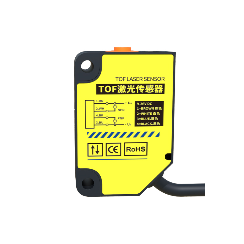
Proper wiring is the cornerstone of reliable photoelectric sensor operation in any industrial automation system. Before connecting a single wire, it is crucial to understand the basic components involved. A typical Xike photoelectric sensor features several key terminals: a power supply input (often labeled V+ and V- or L+ and L-), a load output (usually the switching signal), and sometimes a separate wire for diagnostic or control functions. The power supply provides the necessary operating voltage, commonly 10-30V DC for DC models. The load output is an open-collector transistor (NPN or PNP) that switches on or off to control an external device like a PLC input, relay, or indicator lamp. Misidentifying these terminals is a primary cause of sensor failure or system malfunction, making a clear reference to the sensor's datasheet or housing diagram an indispensable first step.
Essential Tools and Safety Precautions
Gathering the correct tools and adhering to safety protocols ensures a smooth and hazard-free installation process. You will need a set of precision screwdrivers, wire strippers, crimping tools for ferrule connectors, and a digital multimeter for verification. Always begin by disconnecting all power sources to the control cabinet or machine. Verify that the voltage is off using the multimeter. Use only wires with the appropriate gauge and insulation rating as specified for your sensor's current and voltage. For most sensor applications, shielded cables are recommended to minimize electrical noise interference, which can cause erratic switching. Secure the cable shield to the ground terminal at the control panel, ensuring a single-point ground to avoid ground loops. Personal protective equipment, such as safety glasses and insulated gloves, should be worn as a standard practice.
Step-by-Step Wiring Procedure for NPN and PNP Outputs
The wiring procedure differs significantly between the two main output types: NPN (sinking) and PNP (sourcing). For an NPN output sensor, the load is connected between the sensor's output wire (usually black) and the positive supply voltage (V+). When the sensor activates, it connects the output to the common negative (V-), completing the circuit to the load. Conversely, for a PNP output sensor, the load is connected between the sensor's output and the negative supply (V-). Activation connects the output to positive voltage (V+). A common mistake is wiring an NPN sensor to a PNP-compatible PLC input, or vice-versa, resulting in no signal. Always confirm your controller's input type before proceeding. Start by connecting the power wires: brown to V+ (e.g., 24V DC) and blue to V- (0V or common). Then, connect the output wire (black or white) to your target device, and finally, connect any auxiliary wires, such as for a teach-in function or diagnostic LED.
Configuring Operating Modes and Alignment
Once the electrical connections are secure, the sensor must be configured for its specific operating mode. Xike sensors often offer multiple modes like diffuse (proximity), retro-reflective, or through-beam. This is typically set via a selector switch or by teaching the sensor using a button. For through-beam sensors, carefully align the emitter and receiver units. A helpful technique is to temporarily connect the output to a buzzer or bright LED; the clearest alignment is achieved when the audible tone is steadiest or the LED is at its brightest. For diffuse sensors, ensure the target object is within the specified sensing range and that the background material is non-reflective to avoid false triggers. Use the sensor's potentiometer or push-button to fine-tune the sensitivity, ensuring reliable detection without being overly sensitive to ambient light or dust.
Troubleshooting Common Wiring and Operational Issues
Even with careful installation, issues can arise. A systematic troubleshooting approach is key. If the sensor does not power on, first re-check the voltage at the sensor terminals with a multimeter. If power is present but the output doesn't switch, verify the output type (NPN/PNP) compatibility with the load. A frequent issue is incorrect load connection; remember, the load must be in series with the sensor's output. For erratic behavior, check for electrical noise by ensuring proper shield grounding and separating sensor cables from high-voltage AC power lines. If the sensor triggers without a target, reduce the sensitivity or check for reflective backgrounds. Consult the sensor's status LED, which often provides diagnostic flashes for conditions like short-circuit, overload, or alignment errors. Documenting your wiring diagram and settings can save invaluable time during this phase.
Best Practices for Long-Term Reliability and Maintenance
To ensure the photoelectric sensor provides years of trouble-free service, follow established best practices. Use strain relief cable glands to prevent wire pull-out from vibration. Label all wires clearly at both ends for future maintenance. Implement periodic inspection schedules to check for loose connections, cable abrasion, and lens contamination. Clean the lens regularly with a soft, lint-free cloth to maintain optimal optical performance. Avoid using the sensor in environments with excessive condensation or direct spray unless it has an appropriate IP (Ingress Protection) rating. Finally, keep a record of the sensor model and serial number, and bookmark the manufacturer's website for easy access to datasheets, wiring diagrams, and tutorial videos, which serve as excellent resources for future projects or technician training.