Proximity sensors are fundamental components in modern automation, robotics, and countless consumer devices, providing contactless detection of nearby objects. Their performance directly impacts system reliability, making accurate measurement and testing a critical skill for engineers and technicians. Unlike simple on/off checks, proper measurement evaluates the sensor's true operational envelope and health.
The cornerstone of proximity sensor measurement is verifying its sensing distance, often termed the "operating distance" or "Sn." This is the nominal point at which the sensor is guaranteed to switch its output state when a standard target approaches. To measure this, a precisely defined target, typically a square of Fe360 steel for inductive sensors or a white ceramic plate for diffuse photoelectric sensors, is mounted on a calibrated positioning device. The target is slowly moved towards the sensor's active face along the reference axis. The exact point of output signal change is recorded. This process should be repeated multiple times to ensure consistency, as environmental factors and electrical noise can cause minor variations. It is crucial to use the correct standard target material and size specified in the sensor's datasheet, as using an incorrect target will yield inaccurate and non-standard results.
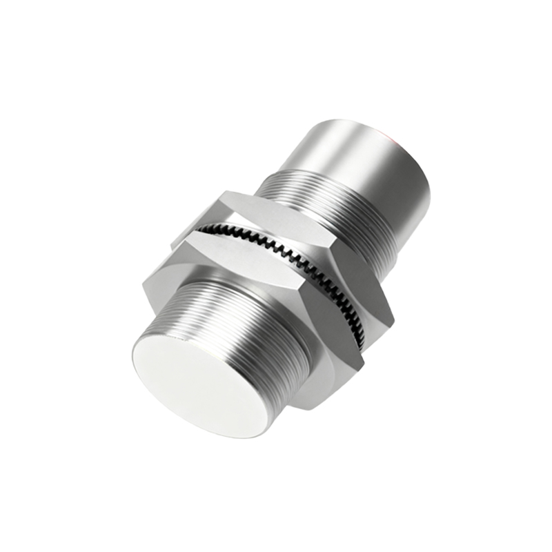
Beyond the nominal operating distance, two other critical thresholds are the "assured operating distance" (Sa) and the "non-operating distance." The assured operating distance is a smaller, guaranteed distance within which the sensor will always detect the target, accounting for variables like supply voltage fluctuations and temperature changes. Measuring this requires testing under minimum specified voltage and potentially elevated temperature conditions. Conversely, the non-operating distance is the point beyond which the sensor is guaranteed not to detect the target. Verifying this ensures the sensor will not false-trigger on objects passing outside its intended range.
Electrical characteristic measurement is equally vital. Using a digital multimeter and an oscilloscope, technicians should monitor the sensor's output signal. For a standard DC 3-wire sensor, key measurements include the residual voltage (or voltage drop) when the output is in the "ON" state. A residual voltage that is too high can prevent proper input recognition by the controller. When the output is "OFF," the leakage current should be measured. Excessive leakage current might falsely trigger a PLC input module configured for a low current threshold. For analog output sensors (e.g., 4-20mA or 0-10V), measurement involves checking the full-scale output. Apply targets at minimum and maximum sensing points and verify that the current or voltage output corresponds accurately to the datasheet specifications, ensuring linearity.
Environmental testing forms the third pillar of comprehensive measurement. Proximity sensors are often deployed in harsh conditions. While basic bench testing is essential, understanding performance under stress is key. Temperature influence can be checked by placing the sensor and target in a climate chamber and repeating the operating distance measurement at the specified minimum and maximum operating temperatures. The sensing distance will typically vary; the datasheet will provide a temperature drift coefficient. Additionally, testing for immunity to electrical noise is important. Operate the sensor near sources of electromagnetic interference, such as variable frequency drives or welding equipment, while monitoring its output for false triggering or instability.
A systematic approach to measurement not only validates new sensors but is also a powerful diagnostic tool for troubleshooting. A sensor that exhibits a significantly reduced operating distance may have a damaged coil (inductive) or lens (photoelectric). Fluctuating output or failure to reach the assured operating distance can point to unstable power supply, excessive load, or electrical noise interference. By methodically measuring and comparing results against the manufacturer's published specifications, one can isolate the root cause—whether it lies in the sensor itself, the target, the installation, or the electrical environment.
Regular verification through measurement forms the basis of predictive maintenance. Periodically checking the operating distance of critical sensors on a production line can reveal gradual degradation before a complete failure causes downtime. This proactive approach, grounded in quantifiable data from simple measurements, maximizes system uptime and ensures the consistent, reliable performance that automated systems demand. Ultimately, mastering these measurement techniques transforms proximity sensors from mysterious black boxes into predictable and manageable components.