Understanding NPN Photoelectric Sensor Fundamentals
Photoelectric sensors are indispensable components in industrial automation, used for detecting the presence, absence, or distance of objects without physical contact. The NPN type is one of the most common output configurations. An NPN photoelectric sensor operates by using a phototransistor as its output switch. In this configuration, the output terminal acts as a sinking output. When the sensor is activated (e.g., when it detects an object), it connects the output line to the common negative voltage (0V or ground). This "sinking" behavior means the load must be connected between the positive supply voltage and the sensor's output wire. Understanding this fundamental principle is crucial before proceeding with any wiring, as it dictates the entire circuit design and compatibility with programmable logic controllers (PLCs) or other control systems.
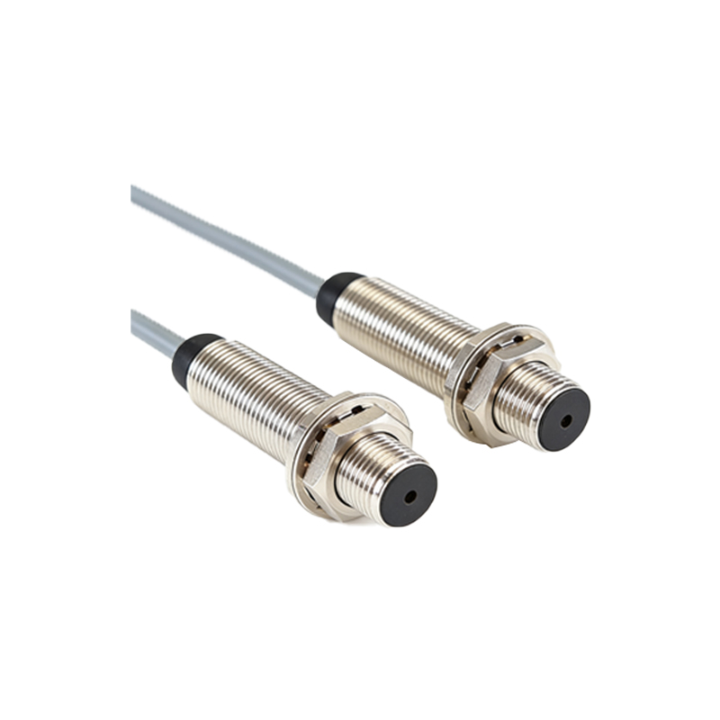
Essential Components and Wiring Tools
Before starting the wiring process, gather all necessary components and tools. You will typically need the NPN photoelectric sensor itself, a suitable DC power supply (commonly 12-24V DC), the load device (such as a PLC input, relay coil, or indicator lamp), and electrical wires of appropriate gauge. Essential tools include wire strippers, crimping tools for terminal connectors, a screwdriver set, and a digital multimeter for verification. Always refer to the sensor's datasheet for its specific voltage range, current rating, and pinout diagram. Most industrial NPN sensors have three or four wires: a brown wire for the positive supply voltage (V+), a blue wire for the common negative or ground (0V), a black wire for the switching output signal, and sometimes a white wire for a complementary output or function. Safety is paramount; ensure the power is completely disconnected during the wiring phase.
Standard Three-Wire NPN Sensor Wiring Procedure
The three-wire system is the industry standard. Follow this step-by-step procedure for a typical setup. First, connect the blue wire from the sensor to the negative terminal (0V or DC-) of your power supply. This establishes the common ground reference. Second, connect the brown wire from the sensor to the positive terminal (V+ or DC+) of the same power supply. This provides operating power to the sensor's internal circuitry. The sensor's LED indicator should now illuminate, showing it has power. Third, you must connect the load. For an NPN sensor, the black output wire is the key. Connect one terminal of your load (e.g., one side of a PLC digital input or a relay coil) to the positive supply voltage (the same V+ line as the brown wire). Finally, connect the other terminal of the load directly to the sensor's black output wire. This completes the circuit. When the sensor activates, it internally connects the black wire to the blue wire (ground), allowing current to flow from V+, through the load, through the sensor's internal switch, to ground, thereby energizing the load.
Connecting to a PLC Input Module
Integrating an NPN photoelectric sensor with a PLC is a frequent application. Most PLC digital input modules are designed to work with either sourcing (PNP) or sinking (NPN) signals. For an NPN sensor, you typically use a sinking input card or configure a universal input for sinking mode. The wiring mirrors the standard procedure. The PLC input point itself is the load. Connect the positive DC supply (e.g., 24V) to one side of the PLC's input terminal (often labeled as the positive common for a group of inputs). Then, connect the sensor's black wire to the specific input terminal you wish to use. Connect the sensor's blue wire to the DC supply's 0V, and its brown wire to the DC supply's 24V. The PLC's internal circuitry completes the path to its own internal common. When the sensor triggers, it sinks current into the PLC input, registering a logic '1' or 'ON' state in the control program. Always verify the PLC manual for voltage compatibility and terminal designations.
Verification, Testing, and Troubleshooting
After wiring, a systematic verification process is essential. First, perform a visual inspection to ensure all connections are secure and correct. Apply power. The sensor's power LED should be steady. Test the sensor's detection function by introducing a target object into its sensing field. Observe the sensor's output LED (if present); it should change state. Simultaneously, use your multimeter set to measure DC voltage. Probe between the sensor's black wire and the blue wire. When the sensor is inactive (no detection), you should read a voltage near the supply level (e.g., 24V), as the output is "open." When the sensor is active, the voltage should drop to nearly 0V, indicating the switch is closed and sinking the output to ground. If the connected load is a lamp or relay, it should energize upon detection. Common issues include no response, which often points to incorrect power polarity or a miswired load. If the load is always on, the sensor output might be wired as sourcing, or the load is connected incorrectly. Ensure the load's voltage and current ratings are within the sensor's switching capacity.
Key Considerations for Reliable Operation
For long-term, reliable operation in harsh industrial environments, several factors must be considered. Always adhere to the specified voltage range; exceeding it can damage the sensor. Consider the load current: the sensor's output has a maximum switching current (e.g., 100mA). If your load draws more current, use an intermediate relay. Pay attention to wiring practices: use shielded cables in electrically noisy environments and ground the shield at one end only to the chassis ground. Maintain the sensor's sensing window clean and free from obstructions. For opposed (through-beam) mode, ensure precise alignment between the emitter and receiver. For diffuse-reflective mode, be mindful of the target object's color, material, and background, as these affect sensing distance. Finally, implement proper circuit protection, such as fuses or surge suppressors, especially in applications with inductive loads like solenoids or motor starters, to protect the sensor's solid-state output from voltage transients.