Introduction to Proximity Sensor E2B Series
The E2B series proximity sensors, developed by Omron, are widely utilized in industrial automation for detecting the presence or absence of metallic objects without physical contact. These sensors operate on the principle of electromagnetic induction, offering high reliability and durability in harsh environments. The E2B lineup includes various models such as cylindrical, rectangular, and slot types, each designed for specific mounting and sensing requirements. Understanding the correct wiring procedures is crucial to ensure optimal performance, safety, and longevity of these sensors in applications like conveyor systems, robotic arms, and machinery safety interlocks.
Key Components and Wiring Terminals
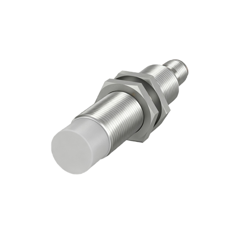
E2B proximity sensors typically feature three or four wires, depending on the output type (NPN or PNP). Common wire colors include brown for positive voltage supply, blue for negative or ground, black for output signal, and white for complementary output in some models. The terminals are clearly marked on the sensor body or connector, with labels such as V+ (brown), V- (blue), and OUT (black). It is essential to refer to the specific datasheet for the model in use, as variations exist between shielded and unshielded versions, which can affect wiring configurations and sensing distances.
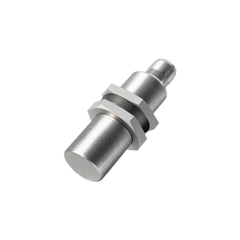
Wiring Diagrams for NPN and PNP Outputs
For NPN output sensors, the black wire connects to the load, which is then linked to the positive supply, while the blue wire is grounded. This configuration is known as sinking output, commonly used in regions like North America. In contrast, PNP output sensors have the black wire connected to the load, which ties to ground, and the brown wire to positive supply, representing sourcing output, prevalent in Europe. Incorrect wiring can lead to sensor malfunction or damage, so always verify the output type marked on the sensor label before installation. Diagrams should be followed meticulously, ensuring proper insulation and secure connections to prevent short circuits.
Step-by-Step Wiring Procedure
Begin by disconnecting power to the control circuit to avoid electrical hazards. Strip the wire ends appropriately and attach them to the sensor terminals using screwdrivers or connectors, as per the manufacturer's instructions. For cylindrical sensors, thread the cable through the mounting nut before connecting to avoid strain. Test the connections with a multimeter to confirm continuity and correct voltage levels. Once wired, power the system and observe the sensor's indicator LED, which should illuminate when a metal target is within range. Adjust the mounting position if necessary to achieve the specified sensing distance, typically up to 15 mm for standard E2B models.
Common Wiring Mistakes and Troubleshooting
Frequent errors include reversing the brown and blue wires, which can cause sensor failure or erratic behavior. Another issue is using incorrect wire gauges, leading to voltage drops or overheating. Ensure wires are rated for the sensor's current capacity, usually below 200 mA. If the sensor does not respond, check for loose connections, contamination on the sensing face, or interference from nearby motors or cables. Shielding the sensor cables and maintaining proper grounding can mitigate noise problems. Consult the troubleshooting guide in the manual for specific error codes or LED blink patterns.
Safety and Maintenance Best Practices
Always adhere to local electrical codes and standards, such as IEC 60947-5-2, when installing E2B sensors. Use protective conduits in environments with high vibration, moisture, or chemical exposure. Regularly inspect wiring for wear and corrosion, especially in outdoor or washdown applications. Keep the sensing area clean from debris like metal chips or oil, which can reduce effectiveness. For maintenance, power down the system before any adjustments and replace sensors if physical damage or performance degradation is observed. Proper wiring not only enhances safety but also minimizes downtime in production lines.
Conclusion and Application Insights
Correct wiring of E2B proximity sensors is fundamental to their reliable operation in industrial settings. By following standardized procedures and avoiding common pitfalls, engineers can ensure accurate detection and seamless integration with PLCs or other control systems. These sensors are versatile, supporting applications from simple object counting to complex automated processes. As technology advances, newer E2B models may offer features like IO-Link connectivity, but the core wiring principles remain consistent. Investing time in proper installation pays off through improved efficiency and reduced maintenance costs over the sensor's lifespan.